Simple USB Relay – I O Modules

Friday, September 26, 2014 | Labels: , , , , , , | 0 comments |
After the success of small modules USB – I / O converters – PUSBIO with MCP2200 circuit intended for development and small batch production, which we introduced in Article MCP2200 USB module and I / O , and recently introduced software for USB I / O modules , now the company introduces new modules Pandatron with relays and optocouplers. [Link]


Continue reading...

Simple VHF FM Aircraft Receiver

| Labels: , , , , | 0 comments |
VHF FM Aircraft Receiver

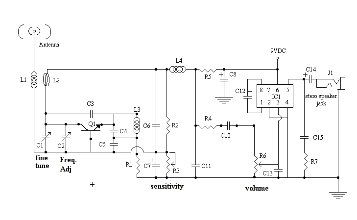
VHF FM Aircraft Receiver is a supererogation receiver developed for listening to FM transmitters but also tunes the aircraft band and the top portion of the FM broadcast band. Receives both AM and FM (107mHz to 135 MHz). You can use this receiver with the any FM transmitter. The receiver is amazingly simple using only one transistor for the receiver section and one IC for the audio section. This circuit is a self-quenching regenerative RF receiver also known as a super regenerative receiver. A superregenerative receiver performs two basic functions. 
 
First it feeds back a portion of the received signal from it’s output in phase to its input; and second a super audible quenching oscillator drives the amplifier through the point of oscillation and maximum sensitivity and then quenches the oscillation repeatedly. This keeps the feedback from driving the circuit into self-oscillation and allows the signal to be regenerated over and over again. In this version of the circuit, both functions are performed by the circuitry associated with Q1. The rest of the circuit, shown to the right of L3 in the schematic, comprise the audio amplification circuit and are centered on the LM386 Audio Amp IC. In this configuration the LM386 is set at a gain of 200 and feeds it’s output to a standard 1/8-inch diameter stereo phone jack. The audio can then be heard by plugging any standard stereo headset into the jack.
Continue reading...

Simple Remote on off Switch Circuit Diagram

| Labels: , , , , , , | 0 comments |
Simple Remote on-off Switch Circuit Diagram. This circuit provides power control without running line-voltage switch leads. The primary of a 6-volt filament transformer is connected between the gate and one of the main terminals of a triac. 

 Simple Remote on-off Switch Circuit Diagram


Simple Remote on-off Switch Circuit Diagram

The secondary is connected to the remote switch through ordinary low-voltage line. With switch open, transformer blocks gate current, prevents the triac from firing and applying power to the equipment. Closingthe switch short-circuits the secondary, causing the transformer to saturate and trigger the triac.

Sourced By circuitsstream
Continue reading...

1 5V to 5V 12V DC DC Converter with LT1073

| Labels: , , , , , , , | 0 comments |
 1.5V to 5V/12V DC/DC Converter with LT1073 Circuit
1.5V to 5V/12V DC/DC Converter with LT1073
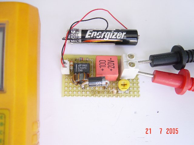
Small 1.5V to 5V or 12V DC/DC converter with LT1073 chip. The IC is available in three different versions, depending on output voltage. Two with fixed output voltage of 5V and 12V, and the most interesting that can be adjusted. The adjustment is done through a voltage divider with two resistors, of mass, output and Terminal 8, internally connected to the voltage comparator IC, which is responsible for stabilizing the output voltage. 
 
1.5V to 5V/12V DC/DC Converter with LT1073
Continue reading...

How to Constructing your own Dual Power Supply Circuits Diagram

| Labels: , , , , , , , , , | 0 comments |
Many times the hobbyist desires to have a simple, dual power supply for a project. Existing power supplies may be large either in power output or physical size. a simple Dual Power Supply is necessary.For most non-critical applications the best & simplest choice for a voltage regulator is the 3-terminal type.The three terminals are input, ground & output.

The 78xx & 79xx series can provide up to 1A load current & it have on chip circuitry to prevent damage in the event of over heating or excessive current. That is, the chip basically shuts down than blowing out. These regulators are cheap, simple to make use of, & they make it practical to design a method with plenty of P C Bs in which an unregulated supply is brought in & regulation is done locally on each circuit board.

This Dual Power Supply project provides a dual power supply. With the appropriate choice of transformer & 3-terminal voltage regulator pairs you can basically build a tiny power supply delivering up to amp at +/- 5V, +/- 9V, +/- 12V, +/-15V or +/-18V. You require to provide the middle tapped transformer and the 3-terminal pair of regulators you require:7805 & 7905, 7809 & 7909, 7812 & 7912, 7815 & 7915or 7818 & 7918.

The user must pick the pair they needs for his particular application.

Note that the + & - regulators do not must be matched: you can for example, use a +5v & -9V pair. However,the positive regulator must be a 78xx regulator, & the negative a 79xx. They have built in plenty of safety in to this project so it ought to give plenty of years of continuous service.

Transformer
This Dual Power Supply design makes use of a full wave bridge rectifier coupled with a centre-tapped transformer. A transformer with a power output rated at at least 7VA ought to be used. The 7VA rating means that the maximum current which can be delivered without overheating will be around 390mA for the 9V+9V tap; 290mA for the 12V+12V and 230mA for the 15V+15V. If the transformer is rated by output RMS-current then the worth ought to be divided by one.2 to get the current which can be supplied. For example, in this case a 1A RMS can deliver 1/(one.2) or 830mA.

Rectifier
They use an epoxy-packaged four amp bridge rectifier with at least a peak reverse voltage of 200V. (Note the part numbers of bridge rectifiers are not standardised so the number are different from different manufacturers.) For safety the diode voltage rating ought to be at least to times that of the transformers secondary voltage. The current rating of the diodes ought to be two times the maximum load current that will be drawn.

Filter Capacitor
The purpose of the filter capacitor is to smooth out the ripple in the rectified AC voltage. Theres dual amount of ripple is determined by the worth of the filer capacitor: the larger the worth the smaller the ripple.The two,200uF is an appropriate value for all the voltages generated using this project. The other consideration in choosing the correct capacitor is its voltage rating. The working voltage of the capacitor has to be greater than the peak output voltage of the rectifier. For an 18V supply the peak output voltage is one.4 x 18V, or 25V. So they have selected a 35V rated capacitor.

Regulators
The unregulated input voltage must always be higher than the regulators output voltage by at least 3V in order for it to work. If the input/output voltage difference is greater than 3V then the excess potential must be dissipated as heat. Without a heat sink three terminal regulators can dissipate about two watts. A simple calculation of the voltage differential times the current drawn will give the watts to be dissipated. Over two watts a heat sink must be provided. If not then the regulator will automatically turn off if the internal temperature reaches 150oC. For safety it is always best to make use of a small heat sink even in case you do not think you will need.

Stability
C4 & C5 improve the regulators ability to react to sudden changes in load current & to prevent uncontrolled oscillations.

Decoupling
The mono block capacitor C2 & C6 across the output provides high frequency decoupling which keep the impedance low at high frequencies.

LED
Two LEDs are provided to show when the output regulated power is online. You do not must make use of the LEDs in the event you do not require to. However, the LED on the negative side of the circuit does provide a maximum load to the 79xx regulator which they found necessary in the coursework of testing. The negative 3-pin regulators did not like a zero load situation. They have provided a 470R/0.5W resistors as the current limiting resistors for the LEDs.

Diode Protection
These protect chiefly against any back emf which may come back in to the power supply when it supplies power to inductive lots. They also provide additional short circuit protection in the case that the positive output is connected by accident to the negative output. If this happened the usual current limiting shutdown in each regulator may not work as intended. The diodes will short circuit in this case & protect the two regulators.

Dual Power Supply Schematic Diagram


Dual Power Supply Schematic Diagram

Continue reading...

Testing A FT245RL Chip with Software

| Labels: , , , , , | 0 comments |
Chips FT245RL testing, checking for the program. It can set the output and input signals to the findings and submit. It is thus possible to enable or disable the 8 channels, for a 8-channel input. It all started a long time ago. Once, when I learned that the computer can be sent off signals that you can manage yourself, immediately began to take interest in the way they can do. It was somewhere in ~ 2002. After browsing the internet and found some examples of how the device can be connected to an LPT Port,.

Testing A FT245RL Chip with Software

Since that time almost all computers have an LPT port, its all gone well. In the LPT port connected LEDs managed a program written by someone that has been written as to support in the MS-DOS. It certainly was not a pleasant appearance, ease of operation ... Was only possible to manage such a procedure, a combination of ... as was intended by its creator. Therefore, once thought myself why can not I create and manage the program as he wants. So began an interest in computer programming and bonding with their devices. [Link]
Continue reading...

Expensive DVD Player by Meridian Audio

| Labels: , , , , , | 0 comments |
Who doesnt have a DVD player today! I know, everybody has one, but I wonder who will have a DVD Player for $20,000! Yes, you read it right. Meridian Audio Ltd presents to you their exclusive range of DVD Players. The company manufactures the worlds most expensive DVD playback machine with prices starting at $19,950.

Worlds Most Expensive DVD Player by Meridian Audio for $20,000!

I am sure you must be thinking of what will you get in return for $20,000! Robert Stuart, the co-founder of Meridian rephrased the question to What do you get for so little? The Model 800 DVD Player is believed to be the pinnacle in audio and video processing technologies. The player plays video recorded in the American NTSC and European PAL systems and uses proprietary software to decode the audio, complex processing to increase picture resolution and extra buffer memory.

So, if you are the one who have a passion for all the most expensive stuff then this superb high definition DVD Player is just for your HDTV!!!![via]
Continue reading...

Simple 500 Watt Inverter Circuit Diagram

| Labels: , , , , , | 0 comments |
This is a Simple 500 Watt Inverter Circuit Diagram. Power inverter is a very useful device which can convert Low voltage from a DC source to high voltage AC. The most common power inverter is 12V to 240V inverter. Perhaps that is because 12V batteries are common. This type of power inverter usually draws current from a DC battery. This battery should be able to provide a high flow of electric current. Normally lead acid batteries can server this purpose well. This current is then converted to 240V square wave alternative current so that we may empower those electric appliances which work on 240V instead of 12V. Inverter falls in the category of expensive devices so many people don’t buy them even they need them. What if I tell you how to build an inverter yourself?

Simple 500 Watt Inverter Circuit Diagram

Simple 500 Watt Inverter Circuit Diagram

I remember when I build my first inverter, I was very happy and I invited a lot of friends to see my homemade inverter. I am sure you will feel the same. Before you start building this inverter circuit diagram, I want to mention that this circuit involves 240V and 500W which can be fatal. You should take all security precautions before building this circuit. Preferably use electricity protective gloves and try not to play with the inverter circuit when it is operational. You will need little to medium knowledge of electronics in order to build this circuit. Alright, let us get to work. There are a lot of inverter circuit diagrams available online; some of them are complex and others are low performance. I have researched on a lot of them but in the end, I designed my own inverter circuit which is comparable to any professionally made inverter but still is simple enough for you to try

NOTE:

There is only one variable resistance in this circuit diagram which is used to adjust frequency of 240V AC output current. You should have a frequency meter to adjust this frequency of 50HZ to 60HZ as per your requirement. Please do not power up any device with your inverter before frequency adjustment because a wrong AC frequency can burn your equipment as well as your inverter.

I have used a two stage regulated power supply to avoid frequency changes with the drop of battery voltage. First stage is 7809 which is a standalone voltage regulator. It converts 12V DC to 9V DC. Then we have used a 22 Ohm resistor and then a zener diode of 8.2V which forces current to stay at 8.2V. The 22 Ohm resistor is there just to aid zener diode. The output frequency of this inverter circuit is square wave so it is not best to power up inductive loads so use it at your own risk. However I do power up fans at home using this inverter and I never had any problems other than a little decrease in fan speed and addition of a little noise

Sourced By : www.circuitsproject.com

PARTS:

1. 2 Resisters 470 Ohm ¼ Watt
2. 3 Resisters 22 Ohm 1 Watt
3. 1 Variable resister 10K
4. 1 Capacitor1uf
5. 1 Capacitor 220uf
6. 1 Zener diode 8.2V
7. 1 IC CD4047
8. 1 IC 7809
9. 1 Transformer 12+12/240 (500W)
10. 2 Transistors D313
11. 12 Power Transistors TIP35C (make two pairs of 6 transistors each connected in parallel)
12. 2 Heat sinks to fit power transistors
13. Some wiring wire (for connections)
14. A Viro-board (To build circuit on)
15.A 12V battery of 12V power supply for testing purposes
Continue reading...

Digital Electronic Lock Circuit Diagram

| Labels: , , , , | 0 comments |
This Digital Electronic Lock Circuit Diagram shown below uses 4 common logic ICs to allow controlling a relay by entering a 4 digit number on a keypad. The first 4 outputs from the CD4017 decade counter (pins 3,2,4,7) are gated together with 4 digits from a keypad so that as the keys are depressed in the correct order, the counter will advance. As each correct key is pressed, a low level appears at the output of the dual NAND gate producing a high level at the output of the 8 input NAND at pin 13.

Read : Cheap Bicycle Alarm Schematics Circuit

Digital Electronic Lock Circuit Diagram

Digital Electronic Lock Circuit Diagram

The momentary high level from pin 13 activates a one shot circuit which applies an approximate 80 millisecond positive going pulse to the clock line (pin 14) of the decade counter which advances it one count on the rising edge.

Read : Emergency Light and Alarm Circuit Diagram

A second monostable, one shot circuit is used to generate an approximate 40 millisecond positive going pulse which is applied to the common point of the keypad so that the appropriate NAND gate will see two logic high levels when the correct key is pressed (one from the counter and the other from the key). The inverted clock pulse (negative going) at pin 12 of the 74C14 and the positive going keypad pulse at pin 6 are gated together using two diodes as an AND gate (shown in lower right corner).

Read : Burglar Alarm With Timed Shutoff Circuit Diagram

The output at the junction of the diodes will be positive in the event a wrong key is pressed and will reset the counter. When a correct key is pressed, outputs will be present from both monostable circuits (clock and keypad) causing the reset line to remain low and allowing the counter to advance. However, since the keypad pulse begins slightly before the clock, a 0.1uF capacitor is connected to the reset line to delay the reset until the inverted clock arrives.

Read : 5 Zone alarm Circuit Diagram

The values are not critical and various other timing schemes could be used but the clock signal should be slightly longer than the keypad pulse so that the clock signal can mask out the keypad and avoid resetting the counter in the event the clock pulse ends before the keypad pulse. The fifth output of the counter is on pin 10, so that after four correct key entries have been made, pin 10 will move to a high level and can be used to activate a relay, illuminate an LED, ect. At this point, the lock can be reset simply by pressing any key. The circuit can be extended with additional gates (one more CD4011) to accept up to a 8 digit code.

Read :  Alarm Control Keypad Circuit Diagram

The 4017 counting order is 3 2 4 7 10 1 5 6 9 11 so that the first 8 outputs are connected to the NAND gates and pin 9 would be used to drive the relay or light. The 4 additional NAND gate outputs would connect to the 4 remaining inputs of the CD4068 (pins 9,10,11,12). The circuit will operate from 3 to 12 volts on 4000 series CMOS but only 6 volts or less if 74HC parts are used. The circuit draws very little current (about 165 microamps) so it could be powered for several months on 4 AA batteries assuming only intermittent use of the relay.
Continue reading...

Simple Emergency Lamp and Turning Indicator Circuit Diagram

| Labels: , , , , , , , | 0 comments |
This is a Simple Emergency Lamp and Turning Indicator Circuit Diagram.White LEDs are replacing the conventional incandescent and fluorescent bulbs due to their high power efficiency and low operating voltage. These can be utilised optimally for emergency lamp and vehicle turning indication. The circuits for the purpose are given here.

Emergency Lamp and Turning Indicator Circuit Diagram
Emergency Lamp and Turning Indicator Circuit Diagram fig 1

Fig. 1 shows the circuit of a white-LED based emergency lamp. You can also use arrays of white LEDs as daytime running lamps in automobiles. In the emergency lamp, seven 1.2V AA-size Ni-Cd cells giving 8.4V have been used as the power source. The brightness is controlled by duty-cycle variation of an astable multivibrator working at 1 kHz. The astable multivibrator is built around IC1. Its output is connected to LED-driver transistor T1. Up to six branches of white LEDs can be connected in parallel, with each branch containing two LEDs in series (only three branches are used here). Depending on the application, different combinations of battery voltages and the number of LEDs in series can be made such as to keep the resistive losses low.

Emergency Lamp and Turning Indicator Circuit Diagram fig 2

The charger circuit for a Ni-Cd battery is shown in Fig. 2. When the battery voltage is less than 9.8V, charging takes place since the voltage at the emitter of transistor T2 (VE) is 9.8V. The value of resistor R8 is chosen such that the battery charges at a rate of 70 mA per hour. The full charge voltage of the battery is 9.8V. When the battery reaches full voltage, the current reduces to approach the tickle charge value of few milliamperes.

Assemble both the circuits shown in Figs 1 and 2 on a general-purpose PCB. LEDs can also be mounted on the reflector of a lamp. After assembling, connect points A and GND of the emergency lamp circuit to the respective points of the battery charger circuit. Now your emergency lamp is ready to work.

To use the emergency lamp, switch on the circuit using switch S1. All the LEDs (LED1 through LED6) will glow to provide sufficient light.

Emergency Lamp and Turning Indicator Circuit Diagram fig 3


Turning indicator shown in Fig. 3 is another application of the LEDs. It can be used for two-wheelers and draws limited power from the dynamo/battery. At low revolutions, headlight dims because of the increase in load. The white LED-based turning indicator circuit draws a fraction of the power drawn by conventional bulbs, and may last longer than the vehicle itself.The circuit comprises two identical sections for left and right turn indications. 

The right turn indicator circuit is built around transistors T3 through T5 and white/yellow LEDs (LED8 through LED13). Similarly, the left turn indicator circuit is built around transistors T4, T6 and T7 and white/yellow LEDs (LED15 through LED20). Transistor T4 and the piezobuzzer are common for both-side indicators.

When you slide switch S2 towards right, blinking LED7, right-front LEDs (LED8 through LED10) and rear LEDs (LED11 through LED13) start blinking. Similarly, when you slide switch S2 towards left, blinking LED14, left-front LEDs (LED15 through LED17) and rear LEDs (LED18 through LED20) start blinking.Transistor T3 acts as the buffer, while transistor T4 drives the buzzer. Transistors T5 and T7 drive the LEDs.The LED array can be built using white LEDs or yellow LEDs depending on the colour of the indicator’s cover. 

In case you use yellow LEDs, keep in mind that the forward drop voltage is around 1.8V for a single yellow LED and therefore the value of the resistance should be changed in accordance with the increase in the number of LEDs in series.Three white LEDs produce the light intensity of six yellow LEDs.


Copyrighted: EFY : Authors: Anantha Keshava and Shireen M. Baretto
Continue reading...

Urg Negative Output from Positive Input Voltage

| Labels: , , , , , , | 0 comments |
There are some applications, such as double-ended sensors and audio amplifiers that require a negative voltage for operation. With limited space on today’s system boards, creating a dedicated negative supply rail would add to the cost and space of the PCB. Hence, it makes sense to generate the required negative voltage from existing positive supply rails in the system.


One such solution using a traditional synchronous step-down regulator is provided by Texas Instruments in an application note entitled “Creating an Inverting Power Supply Using a Synchronous Step-Down Regulator”1. It shows you how to generate a negative voltage from a positive input voltage to the synchronous buck regulator. [Link]
Continue reading...

Simple 50W Electronic Amplifier Circuit Diagram

| Labels: , , , , , | 0 comments |
This Simple 50W Electronic Amplifier Circuit Diagram project is an IC amplifier module from ST Microelectronics, the TDA7294. It is intended for use as a top quality audio class AB amplifier in hi-fi applications. Its low noise and distortion, wide bandwidth and nice output current capability, enabling it to supply high power in to both four ohm and 8 ohm lots. Its both short circuit and thermal protection.

With the addition of a handful of parts and an appropriate power supply, this module will deliver over 50W RMS in to four or 8 ohms-with < 0.1% Total Harmonic Distortion (THD) and < 0.1% Inter-modulation Distortion (IMD). It is also suitable as a replacement power amp stage, or upgrade for plenty of existing amplifiers of between 30W-50W, provided they have an appropriate dual supply, & most do.

The Specifications of the electronic amplifier project there are:

D.C. Input : 35V
Output power : > 50W RMS, 4-8 ohm load.
Gain : 24 dB (30dB modification)
Input sensitivity : one.3V for 50W, 8 ohm
Signal-to-Noise ratio : > 95 dB, (>105 dBA)
Frequency response : approx. 20Hz - 200kHz, �3 dB
Slew rate : > 10V/uS
THD : < 0.01%, 1W-40W, 1kHz
IMD : < 0.01%, 1W

The maximum supply voltage of the IC is +/- 40V. However the maximum dissipation of the IC can be exceeded even at a lower voltage. Therefore the supply voltage used require not be over +/- 35V. This can be constructed using a 50V middle tapped-transformer, a diode bridge rated at 5A (min.) & a pair of electrolytic capacitors, as shown below. A lower secondary voltage transformer could even be used but the reduced DC voltage will lead to less power output in to 8 ohms. You can still receive 50W in to four ohms with only 24V supply rails.

A 36V C.T. transformer will give you approx +/- 25V rails. The-mains transformer used ought to be rated at a maximum of 80VA. In the event you require to run modules in a stereo amplifier you can use a common power supply. In this case the transformer ought to be rated at 150VA or greater.

Electronic Amplifier Circuit Diagram Description

Most of the circuitry is contained within the IC module. The input signal is applied to pin three by capacitor C1 & low-pass filter R1/C2. The filter improves the pulse response & helps cease RF signals. The lower -3dB point is determined-by R2/C1 & R4/C3. This is about 20Hz for the values used. The upper -3dB point is over 200kHz. C7/C8 & C9/C10 provide additional power supply filtering or decoupling.

Simple 50W Electronic Amplifier Circuit Diagram


R3/R4 are the feedback resistors. The gain is 1+R3/R4 which is approx 16 times, or 24dB. In case you need to increase the input sensitivity you may alter the resistors to suit. Changing R3 to 22k would increase the gain to 30dB and lower the input-required for 50W in to 8 ohm, to 0.6V, without affecting performance much. In case you reduce the worth of R4 you will also need to increase C3 to maintain bass response, as this sets the feedback low frequency roll off.

Pin ten is a mute input and pin 9 provides a standby mode. Muting ought to always happen before standby mode is selected. Connecting these pins permanently to the supply rail ensures that the amplifier comes on immediately on power up. Any switch-on clicks may be eliminated by increasing the time constants of R5/C4 and R6/C5 if necessary.

Make definite that a heavy duty heat-sink rated at least one.4 degree C/W or better is used.

Simple 50W Electronic Amplifier Circuit Diagram

Continue reading...

USB Function Generator Based on AD9833

| Labels: , , , , , | 0 comments |
One tool that I’ve been missing at my lab at home is function generator. They tend to be a bit expensive, so I haven’t bought one. I thought this might be a good opportunity to try and make one myself. I found a pretty common DDS (direct digital synthesis) chip, called AD9833. Then just strap a USB-enabled AVR micro there and maybe some analog electronics.


USB Function Generator Based on AD9833

 
This board doesn’t do any of the special analog magic to allow for variable amplitude or offset for the signal. The output is fixed to 0-4v. I’m planning to make another completely analog board for adjusting amplitude and offset. [Link]
Continue reading...

Simple 10 Amp Solar Charge Controller Circuit Diagram

| Labels: , , , , , , , | 0 comments |
This is a Simple 10 Amp Solar Charge Controller Circuit Diagram. The SCC2 is a solar charge controller, its function is to regulate the power flowing from a photovoltaic panel into a rechargeable battery. It features easy setup with one potentiometer for the float voltage adjustment, an equalize function for periodic overcharging, and automatic temperature compensation for better charging over a range of temperatures.

10 Amp Solar Charge Controller Circuit Diagram

10 Amp Solar Charge Controller Circuit Diagram


The goal of the circuit design was to make a charge controller with analog simplicity, high efficiency, and reliability. A medium power solar system can be built with a 12V solar panel up to 10 amps, the SCC2, and a rechargeable battery. The SCC2 works with lead acid, NiCD and NiMH batteries with ratings from less than one to several hundred amp-hours. With the appropriate parts selection, the SCC2 can be operated at 6V, 12V, 24V or other voltages.

Specifications:
  • Maximum solar panel current: 10 Amps
  • Night time battery drain current: approximately 1ma
  • Nominal battery voltage: 6V, 12V or 24V.
  • See the full SCC2 specifications for more information.
Theory:
The SCC2 acts as a medium power DC current switch between the + terminals of the PV and battery. Diode D1 prevents reverse night time current flow from the battery back to the PV panel.

When the PV voltage is high enough to charge the battery, zener diode D2 conducts and turns on transistor Q2. Q2 switches the power for the rest of the circuit on. The circuit is switched off at night. IC2 provides a 5 volt regulated voltage to power the comparator circuits, it also provides a reference voltage for comparator IC1a.

When the battery voltage is below the desired full voltage and needs charging, comparator IC1a turns on and activates Q1 and Q3, this allows the solar charging current to flow into the battery. Note that Q3 is a P-channel mosfet, this allows the circuit to be wired with a common ground for the solar panel and battery. The solar current loop is drawn in heavy lines on the schematic.

When the battery reaches the full charge point, IC1a operates as a comparator based schmidt trigger oscillator, it switches the solar current off and on. The switching causes the battery voltage to oscillate a few tens of millivolts above and below the desired set point. A rail-to-rail op-amp is required for proper operation, 741 style op-amps will not work in this circuit.

The red/green charging/full LED is driven between the output of IC1a and IC1b. IC1b has an inverted version of the IC1a signal. Pin 5 of IC1b only needs an approximate center point to work as an on-off comparator, it is connected to the varying IC1a pin 2 so that it does not require another reference divider circuit.

The resistors and thermistor on the input side of IC1a form a resistive bridge circuit that is used to compare the battery voltage to a reference voltage coming from IC2/R8/R9. The potentiometer adjusts the voltage point around which the circuit will oscillate on full charge. Resistor R7 adds positive feedback to IC1a for a schmidt trigger characteristic and C6 sets the maximum frequency of oscillation. The thermistor provides thermal compensation, as the temperature goes down, the float voltage setting goes up.

The equalize switch, S1a, forces the circuit on for intentional overcharging. Switch S1b and R1 can be used to select a different float voltage range, you can experiment with this by using different values of R1, typically R1 should be greater than 1M.

Alignment:
    Use:
    Connect the solar panel to the SCC2 solar panel input connectors, connect the battery to the SCC2 output connectors. Put the solar panel in the sun, and watch the battery charge up. Systems where the battery is frequently discharged way down should occasionally be run in equalize mode for a few hours or a full day. It is best to monitor the battery voltage during this operation, disable equalization if the battery voltage goes above 16V (12V version).
Continue reading...

Simple Bright Idea USB Lightbulb

| Labels: , , , , | 0 comments |
 Simple Bright Idea USB Lightbulb

Located right at the end of a sturdy and flexible arm, lies the Bright Idea USB Lightbulb which happens to be a fuss-free lamp, sans switches, where it will also not come with a lampshade nor any legs. No sir, it is up to that creative mind of yours to concentrate and deliberate over grand ideas.

 Simple Bright Idea USB Lightbulb

ou will find it emit a soft and soothing blue light as long as it remains plugged into any USB port, where it will shine some reassuring illumination whenever you need to work late into the night. Not only that, it will glow in the dark even when it is not plugged in, how about that for innovation
Continue reading...

Simple FM Transmitter Circuit Diagram

| Labels: , , , , | 0 comments |
This circuit is a simple two transistor (2N2222) FM transmitter. No license is required for this transmitter according to FCC regulations regarding wireless microphones. If powered by a 9 volt battery and used with an antenna no longer than 12 inches, the transmitter will be within the FCC limits.

The microphone is amplified by Q1. Q2, C5, and L1 form an oscillator that operates in the 80 to 130 MHz range. The oscillator is voltage controlled, so it is modulated by the audio signal that is applied to the base of Q2. R6 limits the input to the RF section, and its value can be adjusted as necessary to limit the volume of the input. L1 and C6 can be made with wire and a pencil. The inductor (L1) is made by winding two pieces of 24 gauge insulated wire, laid side by side, around a pencil six times. Remove the coil you have formed and unscrew the two coils apart from each other. 

  FM Transmitter Circuit Diagram

  FM Transmitter Circuit Diagram


One of these coils (the better looking of the two) will be used in the tank circuit, and the other can be used in the next one you build. The antenna (24 gauge wire) should be soldered to the coil you made, about 2 turns up from the bottom, on the transistor side, and should be 8-12 inches long. To make C6, take a 4 inch piece of 24 gauge insulated wire, bend it over double and, beginning 1/2" from the open end, twist the wire as if you were forming a rope. When you have about 1" of twisted wire, stop and cut the looped end off, leaving about 1/2" of twisted wire (this forms the capacitor) and 1/2" of untwisted wire for leads.
Continue reading...

Mini10 W Audio Amplifier

| Labels: , , , | 0 comments |
This design is based on the 18 Watt Audio Amplifier, and was developed mainly to satisfy the requests of correspondents unable to locate the TLE2141C chip. It uses the widespread NE5532 Dual IC but, obviously, its power output will be comprised in the 9.5 - 11.5W range, as the supply rails cannot exceed ±18V.

10 W Audio Amplifier Circuit Diagram

10 W Audio Amplifier Circuit Diagram


As amplifiers of this kind are frequently used to drive small loudspeaker cabinets, the bass frequency range is rather sacrificed. Therefore a bass-boost control was inserted in the feedback loop of the amplifier, in order to overcome this problem without quality losses. The bass lift curve can reach a maximum of +16.4dB @ 50Hz. In any case, even when the bass control is rotated fully counterclockwise, the amplifier frequency response shows a gentle raising curve: +0.8dB @ 400Hz, +4.7dB @ 100Hz and +6dB @ 50Hz (referred to 1KHz).

Notes:

  • Can be directly connected to CD players, tuners and tape recorders.
  • Schematic shows left channel only, but C3, C4, IC1 and the power supply are common to both channels.
  • Numbers in parentheses show IC1 right channel pin connections.
  • A log type for P2 will ensure a more linear regulation of bass-boost.
  • Do not exceed 18 + 18V supply.
  • Q3 and Q4 must be mounted on heatsink.
  • D1 must be in thermal contact with Q1.
  • Quiescent current (best measured with an Avo-meter in series with Q3 Emitter) is not critical.
  • Set the volume control to the minimum and R3 to its minimum resistance.
  • Power-on the circuit and adjust R3 to read a current drawing of about 20 to 25mA.
  • Wait about 15 minutes, watch if the current is varying and readjust if necessary.
  • A correct grounding is very important to eliminate hum and ground loops. Connect to the same point the ground sides of J1, P1, C2, C3 &C4. Connect C9 to the output ground.
  • Then connect separately the input and output grounds to the power supply ground.

Parts:

P1_________________22K   Log.Potentiometer (Dual-gang for stereo)
P2________________100K Log.Potentiometer (Dual-gang for stereo)
R1________________820R 1/4W Resistor
R2,R4,R8____________4K7 1/4W Resistors
R3________________500R 1/2W Trimmer Cermet
R5_________________82K 1/4W Resistor
R6,R7______________47K 1/4W Resistors
R9_________________10R 1/2W Resistor
R10__________________R22 4W Resistor (wirewound)

C1,C8_____________470nF 63V Polyester Capacitor
C2,C5_____________100µF 25V Electrolytic Capacitors
C3,C4_____________470µF 25V Electrolytic Capacitors
C6_________________47pF 63V Ceramic or Polystyrene Capacitor
C7_________________10nF 63V Polyester Capacitor
C9________________100nF 63V Polyester Capacitor

D1______________1N4148 75V 150mA Diode

IC1_____________NE5532 Low noise Dual Op-amp

Q1_______________BC547B 45V 100mA NPN Transistor
Q2_______________BC557B 45V 100mA PNP Transistor
Q3_______________TIP42A 60V 6A PNP Transistor
Q4_______________TIP41A 60V 6A NPN Transistor

J1__________________RCA audio input socket

Power supply parts:

R11_________________1K5  1/4W Resistor

C10,C11__________4700µF 25V Electrolytic Capacitors

D2________________100V 4A Diode bridge
D3________________5mm. Red LED

T1________________220V Primary, 12 + 12V Secondary 24-30VA Mains transformer

PL1_______________Male Mains plug

SW1_______________SPST Mains switch
 

Technical data:

Output power:
10 Watt RMS into 8 Ohm (1KHz sinewave)
Sensitivity:
115 to 180mV input for 10W output (depending on P2 control position)
Frequency response:
See Comments above
Total harmonic distortion @ 1KHz:
0.1W 0.009% 1W 0.004% 10W 0.005%
Total harmonic distortion @ 100Hz:
0.1W 0.009% 1W 0.007% 10W 0.012%
Total harmonic distortion @ 10KHz:
0.1W 0.056% 1W 0.01% 10W 0.018%
Total harmonic distortion @ 100Hz and full boost:
1W 0.015% 10W 0.03%
Max. bass-boost referred to 1KHz:
400Hz = +5dB; 200Hz = +7.3dB; 100Hz = +12dB; 50Hz = +16.4dB; 30Hz = +13.3dB
Unconditionally stable on capacitive loads
 
Continue reading...

Arduino Leonardo vs Uno

| Labels: , , , | 0 comments |
The Arduino team is now shipping their latest creation – the Leonardo. It is the first Arduino to use Atmelʼs ATmegaXU4 series chip with built-in USB. This change is big and it has big benefits. In addition to the built-in USB, it offers more digital and analog pins. This comprehensive guide gives you the details you need to know to start using it – pinout differences, hardware capabilities, new software libraries and more. [Link]
Arduino Leonardo vs Uno – What’s New
Continue reading...

Simple Remote control tester Circuit Diagram

| Labels: , , , , , | 0 comments |
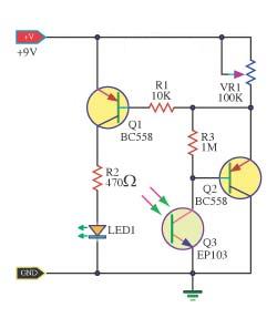
This is the simple Remote control tester circuit diagram. When the remote control is not working, first check the battery before, It may be loss.If it is good,so detect transmit infrared light device.However, because the human eye can not see infrared light,so can not know how good or bad.But the photo transistor can use to detect infrared light. 

This circuit so use this photo transistor is the light receiver from the remote control.If it is nice to have the bias current of the transistor BC558.It runs a current flows through the LED,so the LED bright.The remote control that works correctly. The variable resistor VR1 is used to adjust the sensitivity of the circuit.

 Remote control tester circuit diagram
 
 Remote control tester circuit diagram
Continue reading...

Scalable 12V Solar Power System and Battery Charge Controller

| Labels: , , , , , , , , | 0 comments |
An unconventional, scalable high efficiency 12V solar power system and battery charge controller with low voltage cutout to protect the battery. (ideal for systems of 50W or less). The most common solar charger consists of a Schottky diode to prevent the battery from draining into the PV panel and a shunt regulator that effectively short circuits the panel once the battery is fully charged.

Scalable 12V Solar Power System and Battery Charge Controller

One problem with this approach is diode losses and the resulting heat. If a 50W 12V panel supplies 4A to the battery, the Schottky diode will drop about 0,4V across it dissipating about 1,6W of heat. This requires a heat sink and loses power to heat. The problem is that there is no way of reducing the volt drop, paralleling diodes may share current, but the 0,4V will still be there. The circuit uses a MOSFET in stead of the usual diode and the primary power loss is resistive. [Link]
Continue reading...

A Li Ion Battery Charger with Load Sharing MCP73837

| Labels: , , , , , , , , | 0 comments |
Batteries often serve as the main energy source for portable electronic devices. Although they depend on batteries, portable consumer electronic products, such as GPS devices and multi-media players, often consume energy directly from an ac-dc wall adapter or accessory power adapter (or “Auto Adapter”) when the battery is low or the device is in a stationary mode. Due to their cost effectiveness over their useful life, rechargeable batteries are often used for the power source of the portable electronic device.


Designing A Li-Ion Battery Charger with Load Sharing - MCP73837

 
Attributes such as “relatively high energy density” and “maintenance free” make Lithium-Ion (Li-Ion) batteries popular in the portable consumer electronic products. Refer to the application note, AN1088, “Selecting the Right Battery System For cost Sensitive Portable Applications While maintaining Excellent Quality” (DS01088) for characteristics of Li-Ion batteries. Some examples of how to properly design with Li-Ion batteries will be discussed in this application note. [Link]
Continue reading...

Simple 3 volt to 9 volt with LMC555 Circuit Diagram

| Labels: , , , , , , , , | 0 comments |
Simple 3 volt to 9 volt with LMC555 Circuit Diagram. This is a Build a 3 volt to 9 volt with LMC555 Circuit Diagram. This dc converter is built with the CMOS version of 555 timer. You can get 12V too if you change the zener diode to a 12V version.

3 volt to 9 volt with LMC555 Circuit Diagram


Build a 3 volt to 9 volt with LMC555 Circuit Diagram

Continue reading...

Crystal cMoy Freeform Headphone Amplifier

Tuesday, September 23, 2014 | Labels: , , , , | 0 comments |
Well the time has come to pour the clear casting resin .I have say I have been putting this off for some time ,but it all turned out well in the end as you can see below :) [Link]

Stunning Crystal cMoy Freeform Headphone Amplifier
Continue reading...

Build a Telephone Record Control Circuit Diagram

| Labels: , , , , , , | 0 comments |
This simple Telephone Record Control Circuit Diagram will allow you to connect any tape recorder that has a mic and remote input to a phone line and automatically record both sides of a conversation when ever the phone is in use. You will need to take a couple of voltage readings before connecting the circuit. First determine the polarity of your phone line and connect it to the circuit as shown and then determine the polarity of the remote input and connect it to the circuit.

Circuit operation is as follows. When the phone is on hook the voltage across the phone line is about 48volts dc. When the phone is off hook the voltage will drop to below 10volts dc. When the line voltage is at 48volts the FET is off which causes Q2 and Q3 to be off. When the phone is picked up the FET turns on along with Q2 and Q3 which turns your recorder on. The tape recorder must be in the record mode at all times. As you can see the power source for the circuit is the phone line. 

Telephone Record Control Circuit Diagram

Telephone Record Control Circuit Diagram
 
Continue reading...

Tracking Battery Charger IC Supports Solar Power Systems

| Labels: , , , , , , , | 0 comments |
Individual solar-panel systems produce dc power for remote applications while also storing energy in a rechargeable battery supported by a battery-charger IC. In non-utility grid applications solar panels produce dc power for emergency roadside telephones, navigation buoys, and other remote loads. Virtually all 12-V-system solar panels comprise a series of photovoltaic cells that have a maximum output power of less than 25 W.
Power-Tracking Battery-Charger IC Supports Solar-Power Systems
In producing this power the solar-panel system uses a battery to provide power when the panel is “dark.” The rechargeable battery can supply power for long periods of time, requiring a charger that can properly operate a solar panel. Meeting this need is Linear Technology’s LT3652 monolithic buck-charger IC, which operates with a single solar panel.

The IC uses average-current-mode control-loop architecture to provide constant current/constant voltage (CC/CV) charge characteristics with a programmable charge current. The charger can be programmed to produce a 14.4-V float voltage. Housed in a 3- × 3-mm DFN-12 package, the IC can charge a variety of battery configurations, including up to three Li-Ion/Polymer cells in series, up to four Lithium Iron Phosphate (LiFePO4) cells in series, and sealed lead-acid batteries up to 14.4 V. [Link]
Continue reading...

Simple Accurate Foot Switch Circuit Diagram

| Labels: , , , , , | 0 comments |
Certain industrial controls require accurate switching operations. For example, in case of a foot-switch for precise drilling work, even a small error in switching may cause considerable loss. This low-cost but accurate foot-operated switch can prevent that.

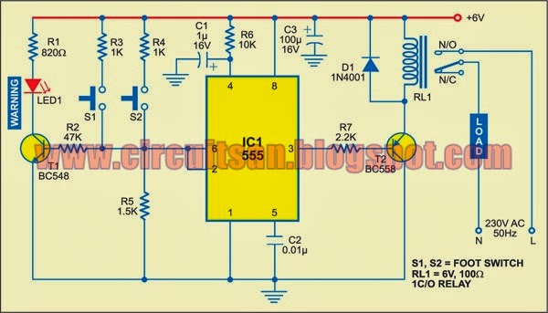
IC NE555 is wired in one-shot mode. Its output pin 3 goes high only when both switches S1 and S2 are pressed simultaneously. You can release any one of the switches without changing the output state. When you release both the switches, the output goes low.

Simple Accurate Foot-Switch Circuit Diagram

Simple Accurate Foot-Switch Circuit Diagram

The switches are placed under a foot paddle as shown in Fig. 2. LED1 is used as a warning indicator. If either S1 or S2 gets pressed erroneously, LED1 blinks to warn the operator. The operator can then withdraw his foot in case of a mistake or depress the other switch also to trigger the circuit. LED1 is to be mounted on the operator’s desk.

The circuit operation is simple. Resistors R2, R3 and R4 form a voltage divider. IC NE555 has two comparators, a flip-flop and power output section built into it. Pressing either S1 or S2 puts the input voltage between the upper comparator (2/3Vcc) and the lower comparator (1/3Vcc). Thus, it has no effect on the state of the internal flip-flop of IC NE555. Pressing the two switches simultaneously sets the flip-flop and the output of NE555 goes high. Transistor T2 energises relay RL1 for driving the load.


Releasing any of the switches brings the comparator voltage back to the initial level inside NE555 and it has no effect on the state of the flip-flop. Releasing both the switches brings the input level with respect to ground below the low trigger level, and thus it resets the output.

Use of the voltage divider results in stable operation over the entire permissible supply voltage range. The RC circuit at pin 4 provides power-on reset.

When only S1 is pressed, R3 (1 kilo-ohm) is less than R5 (1.5 kilo-ohms) and IC1 is not triggered. However, transistor T1 (BC548) gets forward biased and LED1 glows. When both S1 and S2 are pressed, the effective resistance between +Vcc and pin 2 of IC1 is about 500 ohms, which is less than R5 (1.5 kilo-ohms), and IC NE555 gets triggered.


Sourced By: EFY Author Name : Kaushik Hazarika
Continue reading...

DS3231M Real Time Clock Breakout

Friday, September 19, 2014 | Labels: , , , , | 0 comments |
The DS3231M breakout board is a compact breakout board for the new DS3231M high precision real time clock chip. With it, you can add timekeeping and alarm functionality to any Arduino (or other microcontroller that supports the I2C/TWI protocol).


The board comes with an onboard CR1220 backup battery (keeps time when main power is disconnected). All pins on the chip are broken out, allowing you to use extra features such as 1Hz and 32kHz square wave output, interrupt on alarm and reset. [Link]
Continue reading...

Multiple Applications of High Power LEDs

| Labels: , , , , , | 0 comments |
Nowadays, high-power light-emitting diodes (LEDs) LXHLMW1C are available in the market. These white LEDs contain indium-gallium-nitrogen (InGaN). The LEDs’ emitting capacity is 20 candela (Cd). We can use these LEDs for automatic garden lighting and wide voltage operation by applying different voltages.

Multiple Applications of High-Power LEDs


Fig. 1: Circuit for automatic garden lighting

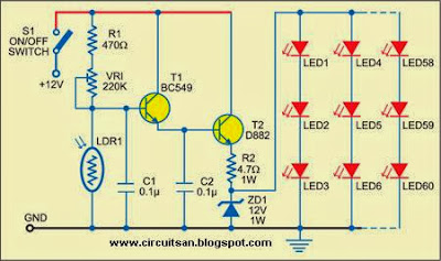
Fig. 1 shows the circuit for automatic garden lighting. Switch S1 connects 12V to the circuit built around transistors T1 and T2. Light-dependent resistor LDR1 is used to sense the light intensity and preset VR1 is used to adjust the threshold of light. The resistance of LDR remains low in daylight and high at night (in darkness).

In the morning, light falls on LDR1 and transistors T1 and T2 are cut-off. As a result, 12V supply is not available to the LEDs. In the evening, when no light falls on LDR1, transistors T1 and T2 conduct to provide 12V to the LEDs. This turns on all the LEDs (LED1 through LED60). The on/off switching level can be adjusted by 220 kilo-ohm preset according to the intensity of the light.

The emitting capacity of LEDs (UW-510CWH) used here is 8 Cd. Since a total of 60 of these LEDs have been used, this unit will provide luminous intensity equivalent of 480 Cd. The LEDs are arranged in twenty rows, with each row having three LEDs in series. The input voltage is approximately 12V and all the LEDs are spaced 1 to 1.5 cm apart.

Fig. 2: Circuit for wide-voltage operation

The entire circuit, except LDR1, can be assembled on any general-purpose PCB. House the PCB in a box and, using two long wires, mount LDR1 at a place where light falls on it directly. Now place the unit in your garden.

You can use the switching section for other systems as well. You just need to remove the LED section from the circuit and connect the switching section to the desired system. So the system will now automatically switch on in the evening and switch off in the morning.

Fig. 3: Pin configuration

Fig. 2 shows a wide-voltage operation circuit. Here, the high-power LED61 (LXHLMW1C) gives a power equivalent of 20 Cd. This LED has a metallic back for mounting on a heat-sink. Its rated maximum input DC voltage and current are 3.6V and 350 mA, respectively. Regulator IC LM317 (IC1) provides a constant voltage of 4.7V. Resistors R3 and R4 limit the current through the LED. The LED is very sensitive to voltage inputs. In the 2.5V-3.5V region, each millivolt variation changes the current through the LED logarithmically. Transistors BC549 and D882 (T3 and T4) and resistor R6 provide a constant current to LED61. The unit gives a constant lighting for voltages ranging from 7V to 25V.

Fig. 3 shows pin configuration of regulator LM317 and transistors D882 and BC549. Use heat-sinks in regulator LM317 and transistor D882 before soldering them onto the PCB.
Continue reading...

Simple Cmos Motorcycle Alarm Circuit Diagram

| Labels: , , , , , | 0 comments |
This Simple Cmos Motorcycle Alarm Circuit Diagram features an intermittent siren output and automatic reset. It can be operated manually using a key-switch or a hidden switch; but it can also be wired to set itself automatically when you turn-off the ignition. By adding external relays you can immobilize the bike - flash the lights etc.

Cmos Motorcycle Alarm Schematic Diagram

Cmos Motorcycle Alarm Circuit Diagram

Notes
Any number of normally-open switches may be used. Fit "tilt" switches that close when the steering is moved or when the bike is lifted off its side-stand or pushed forward off its centre-stand. Use micro-switches to protect removable panels and the lids of panniers etc.

Once activated - the rate at which the siren switches on and off is controlled by R9 & C5. For example - increasing the value of C5 will slow it down - while reducing the value of R9 will make it faster.

While at least one switch remains closed the siren will sound. About thirty seconds after all of the switches have been opened, the alarm will reset. How long it takes to switch off depends on the characteristics of the actual components used. You can adjust the time to suit your requirements by changing the value of R6 and/or C4.

The circuit is designed to use an electronic Siren drawing 300 to 400mA. Its not usually a good idea to use the bikes own Horn because it can be easily located and disconnected. However, if you choose to use the Horn, remember that the alarm relay is too small to carry the necessary current. Connect the coil of a suitably rated relay to the "Siren" output. This can then be used to sound the Horn - flash the lights etc.

The circuit board and switches must be protected from the elements. Dampness or condensation will cause malfunction. Connect the 1-amp in-line fuse AS CLOSE AS POSSIBLE to your power source. This is VERY IMPORTANT. The fuse is there to protect the wiring - not the alarm. Exactly how the system is fitted will depend on the make of your particular machine - so Im unable to provide any further help or advice in this regard.

The quiescent (standby) current of the circuit is virtually zero - so there is no drain on the battery. If you want to operate the alarm manually use a key-switch or a hidden switch connected to the "off/set" terminals. For automatic operation connect a wire from the ignition circuit to the "ignit" terminal. Then every time you turn-off the ignition - the alarm will set itself. Remember that this wire from the ignition switch is not protected by your 1-amp inline fuse. So unless its run is very short - fit the wire with its own 1-amp fuse as close as possible to its source.

When you set the alarm - if one of the switches is closed - the siren will sound. This could cause annoyance late at night. A small modification will allow you to Monitor The State Of The Switches using LEDs. When the LEDs are all off - the switches are all open - and its safe to turn the alarm on.

Veroboard Layout

Cmos Motorcycle Alarm Circuit Diagram


Continue reading...

Tactful Triac Controller Circuit Diagram

| Labels: , , , , | 0 comments |
Simple Tactful Triac Controller Circuit Diagram. This is the sensitive triac circuit in this circuit the single transistor connected between the capacitor and the common side of the ac line allows a logic-level signal to control this triac power circuit. Resistor R2 prevents false triggering of the triac by the trickle current through the diac.

Simple Tactful Triac Controller Circuit Diagram


Simple Tactful Triac Controller Circuit Diagram

Sourced By: Circuitsstream
Continue reading...

Build a18W Car Stereo Amplifier Circuit Diagram

| Labels: , , , , , , | 0 comments |
This automobile stereo amplifier project is a class AB audio power amplifier using the Hitachi HA13118 module. It not only can be used in automobile application but also in any transportable or home amplifier process. It is simple to construct & has a maximum of outside parts. The module has a high power output from a low voltage supply using the bridge tied load system, & a high gain of 55dB.

This project will be useful in applications where the input signal is a low level, without requiring the use of a separate pre-amplifier. This IC module has a built in surge protection circuit, thermal shutdown circuit, ground fault protection circuit & power supply fault protection circuit making it reliable.
The Specifications of this project 
D.C. Input : 8 – 18V at 1-2 A

Power output : 18W maximum, 4 ohm load, 18V DC supply

S/N ratio : > 70 dB

THD : < 0.2% @ 1W

Freq. Response : ~ 30 Hz to 30 kHz, –3 dB

Input level : < 25 mV, for full output (G > 50dB)

Input Impedance : ~ 30 k ohm

The supply voltage necessary for this project is 8 -18V DC, at least one to two Amps. Maximum output power will only be obtained with a power supply of 18V at greater than two A, using a four ohm speaker. The power supply ought to be well filtered to reduce mains hum, a regulated supply will reduce noise even further. Additional filtering is unnecessary if operating from a battery supply.

Circuit Diagram Description

Most of the circuitry is contained within the amplifier module. C10 is the input coupling capacitor and blocks DC from the input. C11 bypasses any RF which may be present at the input. C1 & C2 provide an AC ground for the inverting inputs of the IC. R1/C7 and R2/C8 provide a high frequency load for stability with difficult speakers. C five & C six provide bootstrap feedback for the IC. C9 & C12 provide power supply filtering.

Build a18W Car Stereo Amplifier Circuit Diagram

An externally mounted logarithmic potentiometer of between 10k ohm and 50k ohm, is used depending on the desired input impedance. The impedance ought to be keep as high as feasible for a guitar amp, unless using a separate pre-amp. Make sure-that the heat sink is mounted to the module.


Continue reading...

Build a Wideband UHF Amplifier Circuit Diagram

| Labels: , , , , , , | 0 comments |
This is the simple wide band UHF amplifier with high-performance fetes. The amplifier circuit is designed for 225 MHz center frequency, 1 dB bandwidth of 50 MHz, low input VSWR in a 75-ohm system, and 24 dB gain Three stages of U310 FETs are used in a straight forward design.


Wide-band UHF Amplifier Circuit Diagram


Wideband UHF Amplifier Circuit Diagram

Continue reading...

Build a PC Based Timer Circuit Diagram

| Labels: , , , , , , | 0 comments |
Timers are very useful both for industrial applications and household appliances. Here is a PC-based timer that can be used for controlling the appliances for up to 18 hours. For control, the timer uses a simple program and interface circuit. It is very cost-effective and efficient for those who have a PC at workplace or home. The tolerance is ±1 second.

The circuit for interfacing the PC’s parallel port with the load is very simple. It uses only one IC MCT2E, which isolates the PC and the relay driver circuits. The IC prevents the PC from any short circuit that may occur in the relay driver circuit or appliance. The glowing of LED1 indicates that the appliance is turned on. Transistor BC548 is used as the relay driver.

The program code is written in ‘C’ language and compiled using ‘Turbo C’ compiler. When the program is run, it prompts the user to input the time duration in seconds or minutes to control the appliance. After entering the required timing, press any key from the keyboard.

Suppose you input the total duration as ‘x’ minutes, of which ‘on’ and ‘off’ durations are ‘y’ and ‘z’ minutes, respectively. The program will repeat the on-off cycle for x/(y+z) number of times. After completion of the total time, to repeat the cycle, you will have to reset the time in the program to activate the circuit.

PC-Based Timer Circuit Diagram

PC-Based Timer Circuit Diagram


The program uses two bytes for storing integer type data. So when input is given in terms of seconds or minutes, it can hold 216–1=65,535 seconds or 18 hours at the maximum. The sleep() function in the program is used to hold the appliance in ‘on’ or ‘off’ condition for the ‘on’ and ‘off’ periods as entered by the user against prompts. The sound() function is used to give a beep during ‘on’ condition of the appliance.

EFY note. The source code and executable file of this program have been included in this month’s EFY-CD.

Sourced By: EFY Author Akshy

Continue reading...

Simple DC to AC Inverter Circuit Diagram

| Labels: , , , , , , | 0 comments |
Simple DC to AC Inverter Circuit Diagram

Simple DC to AC Inverter

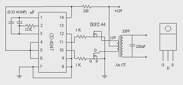
This DC to AC inverter circuit work based on unstable multi vibrator does. In this circuit, IC CD4047 is chosen as a heart of unstable multivibrator, because this IC type gives a complementary output that has opposite phase to another ( pin 10 and 11 as seen in Figure 1), and has 50 % duty cycle that satisfy to generate a pulse for inverter.
Continue reading...

An LCD Clock Kit Suitable for Beginners with Open Source Arduino Firmware

| Labels: , , , , , , , , , , , | 0 comments |
Simpleclock is an easy to assemble attractive 4-digit 7-segment LED display clock with temperature and alarm function. It is available in three display colors: Red, Blue and White. It comes as a kit of through-the-hole parts and can be soldered by any person with basic soldering experience. An attractive acrylic stand is included. [Link]

Continue reading...

Simple Frequency Comparator Circuit Diagram

| Labels: , , , , | 0 comments |
This is a digital circuit may arrive at your need, This circuit is a simple frequency comparator. The circuit Input 1 is used as a gating period, during which a single rising edge on input 2 will cause a logic 1 output-any other number, indicating non-identical frequencies causes a logic 0 output. ICla converts input 1 to a narrow pulse which initializes IC2 which forms a two-stage shift register clocked by input 2. 

 Best Frequency Comparator Circuit Diagram

Best Frequency Comparator Circuit Diagram
On the first edge of input 2 a logic 1 appears on the output of IC2b and for all subsequent inputs a logic 0 is present. At the end of the gating period this output is latched by IC3 forming the lock output.As this is only valid for one input period a monostable is added to the output to enable, for example, visual monitoring of the output. Either output from IC3 can be used depending on which state is most important. As connected the failure state is indicated. 
 
Sourced by : Circuitsstream
Continue reading...

Simple Photodiode Alarm Circuit Diagram

| Labels: , , , , | 0 comments |
Continue reading...

Robot Shield for Arduino

| Labels: , , , | 0 comments |
The idea behind this post is to bring together some robot designs and transform them in a new device with new hardware and standard software (arduino of course) and so easier to use.  These robots have three things in common: a mechanical structure, the hardware and the software. While the mechanical part is necessarily different.

Robot Shield for Arduino
We wanted to understand if there was a hardware board that could be common, with a unique development system. The choice, quite obviously, has the Arduino board, which with its development environment is perfect to create similar projects.
Continue reading...