Showing posts with label switch. Show all posts

Simple Remote on off Switch Circuit Diagram

Friday, September 26, 2014 | Labels: , , , , , , | 0 comments |
Simple Remote on-off Switch Circuit Diagram. This circuit provides power control without running line-voltage switch leads. The primary of a 6-volt filament transformer is connected between the gate and one of the main terminals of a triac. 

 Simple Remote on-off Switch Circuit Diagram


Simple Remote on-off Switch Circuit Diagram

The secondary is connected to the remote switch through ordinary low-voltage line. With switch open, transformer blocks gate current, prevents the triac from firing and applying power to the equipment. Closingthe switch short-circuits the secondary, causing the transformer to saturate and trigger the triac.

Sourced By circuitsstream
Continue reading...

Simple Accurate Foot Switch Circuit Diagram

Tuesday, September 23, 2014 | Labels: , , , , , | 0 comments |
Certain industrial controls require accurate switching operations. For example, in case of a foot-switch for precise drilling work, even a small error in switching may cause considerable loss. This low-cost but accurate foot-operated switch can prevent that.

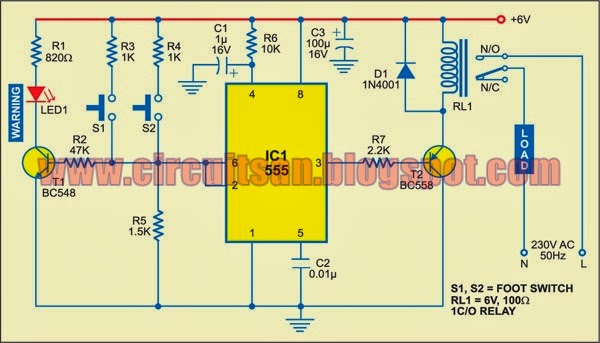
IC NE555 is wired in one-shot mode. Its output pin 3 goes high only when both switches S1 and S2 are pressed simultaneously. You can release any one of the switches without changing the output state. When you release both the switches, the output goes low.

Simple Accurate Foot-Switch Circuit Diagram

Simple Accurate Foot-Switch Circuit Diagram

The switches are placed under a foot paddle as shown in Fig. 2. LED1 is used as a warning indicator. If either S1 or S2 gets pressed erroneously, LED1 blinks to warn the operator. The operator can then withdraw his foot in case of a mistake or depress the other switch also to trigger the circuit. LED1 is to be mounted on the operator’s desk.

The circuit operation is simple. Resistors R2, R3 and R4 form a voltage divider. IC NE555 has two comparators, a flip-flop and power output section built into it. Pressing either S1 or S2 puts the input voltage between the upper comparator (2/3Vcc) and the lower comparator (1/3Vcc). Thus, it has no effect on the state of the internal flip-flop of IC NE555. Pressing the two switches simultaneously sets the flip-flop and the output of NE555 goes high. Transistor T2 energises relay RL1 for driving the load.


Releasing any of the switches brings the comparator voltage back to the initial level inside NE555 and it has no effect on the state of the flip-flop. Releasing both the switches brings the input level with respect to ground below the low trigger level, and thus it resets the output.

Use of the voltage divider results in stable operation over the entire permissible supply voltage range. The RC circuit at pin 4 provides power-on reset.

When only S1 is pressed, R3 (1 kilo-ohm) is less than R5 (1.5 kilo-ohms) and IC1 is not triggered. However, transistor T1 (BC548) gets forward biased and LED1 glows. When both S1 and S2 are pressed, the effective resistance between +Vcc and pin 2 of IC1 is about 500 ohms, which is less than R5 (1.5 kilo-ohms), and IC NE555 gets triggered.


Sourced By: EFY Author Name : Kaushik Hazarika
Continue reading...

Switch ON OFF Touch or with Push Button Circuit Diagram

Friday, September 19, 2014 | Labels: , , , , , , , , , | 0 comments |
Here we have three choices, with which we can make electronic switches that use our touch or pressing (push button). We thus exploit the very big resistance of entry, that present the gates CMOS. In the fig.1 we have two gates NAND or NOR (IC1), connected as R-S flip-flop. Just as we press the switch S1, the exit 3 it becomes [H], even it is maintained in this situation.

To change the situation, it should we press switch S2. Now exit 3, takes price (L), reversely exit 4 becomes (H). In order to we maintain the situation that we want, we can connect at parallel with the corresponding switch, a capacitor C=100nF. This entry will always drive the corresponding exit to logic (L), immediately afterwards the benefit of supply to the circuit.

Switch ON-OFF Touch or with Push Button Schematic

Switch ON-OFF Touch or with Push Button Schematic


In the fig. 2, we have a circuit of inverter CMOS, in the entry of which is applied logic situation (H), from the resistance R, which the other end of, is in the supply. Exit 2 has situation (L).

When we press switch S2, in the entry of 3 IC2, we have situation (L), this it goes to the ground, the exit now becomes (H). This situations are maintained as long as we keep pressed switch S2 and they change immediately hardly the touch. If we want opposite logic operation then it will be supposed we connect the resistance R, in the ground and switch S2, in the supply. The same logic we will have if we replace gate IC2, with a gate NAND or NOR, as it appears in the fig. 3, the result is the himself.

Because the situation in the case of fig.1 and 3, does not remain constant and change when we pull our finger , in order to him we retain, it should we connect a J-K or D flip-flop as T, after the IC2 and IC3. Thus the flip-flop, will change situation, each time where we will touch the switch or will touch the contacts and him it will retain.

All the switches can be replaced with contacts, it is enough we replace also resistances R with the price of 10MΩ. The Resistances R when we use pressing switches can are, from 100KΩ until 1MΩ. Because when we use contacts instead of switches, the noise can turn on the gates of fig. 2 and 3, then can place a capacitor 100nF, parallel with the contacts.[via]
Continue reading...

Switch Wiring Diagram Variationelectrical Online

Friday, May 31, 2013 | Labels: , , , , | 0 comments |
Wiringlight on Jeep Grand Cherokee Radio Adaptor Wiring Harness   Circuit Schematic
Jeep Grand Cherokee Radio Adaptor Wiring Harness Circuit Schematic.


Wiringlight on Wiring Trailer Lights
Wiring Trailer Lights.


Wiringlight on Wiring A Light Fitting
Wiring A Light Fitting.


Wiringlight on Wiring A Switch With Light In Middle Of Circuit
Wiring A Switch With Light In Middle Of Circuit.


Wiringlight on Light With Outlet 2 Way Switch Wiring Diagram
Light With Outlet 2 Way Switch Wiring Diagram.


Wiringlight on Smith Brothers Services   Sealed Beam Plow Light Wiring Diagram
Smith Brothers Services Sealed Beam Plow Light Wiring Diagram.


Wiringlight on Thread  Wiring Clipsal Saturn Light Switches
Thread Wiring Clipsal Saturn Light Switches.


Wiringlight on The Method I Used For Wiring The Lights For The
The Method I Used For Wiring The Lights For The.


Wiringlight on Way Switch Wiring Diagram Variation  3   Electrical Online
Way Switch Wiring Diagram Variation 3 Electrical Online.


Wiringlight on How To Wire Two Lights Controlled From One Switch
How To Wire Two Lights Controlled From One Switch.


Continue reading...

Capacitor and Resistor in One Switch Box

Wednesday, May 1, 2013 | Labels: , , , , , , | 0 comments |
It would be nice and comfortable doing our work and what we needed are readily available to save time and effort. It lessens the hassle of looking for missing pieces or even using multiple devices to check the accuracy and effectiveness of the equipments we are using.

pacitor and Resistor in One Switch Box
Just like this switch box that has a capacitor and resistor in one unit. It will be easier and faster to check the capacitance and resistance by switching the knobs. This device may look old-fashioned but can really come very handy. This is simple and not that expensive to make and very useful in electronic projects or for the purpose of collecting devices for future use.

pacitor and Resistor in One Switch Box


Source : extreamcirciuts
Continue reading...