Showing posts with label with. Show all posts

1 5V to 5V 12V DC DC Converter with LT1073

Friday, September 26, 2014 | Labels: , , , , , , , | 0 comments |
 1.5V to 5V/12V DC/DC Converter with LT1073 Circuit
1.5V to 5V/12V DC/DC Converter with LT1073
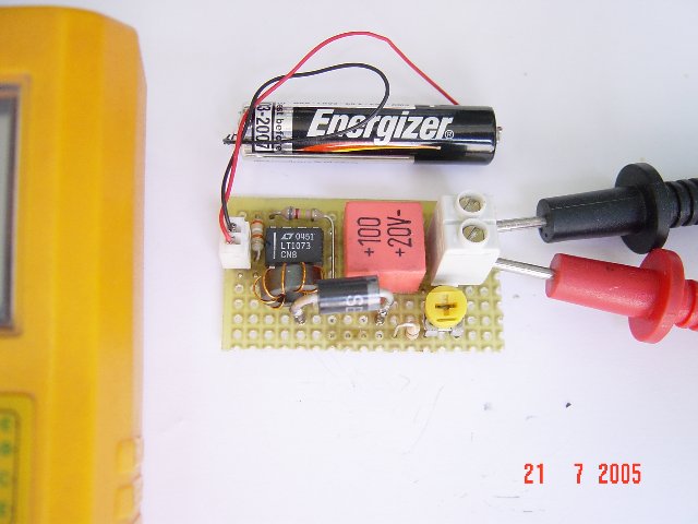
Small 1.5V to 5V or 12V DC/DC converter with LT1073 chip. The IC is available in three different versions, depending on output voltage. Two with fixed output voltage of 5V and 12V, and the most interesting that can be adjusted. The adjustment is done through a voltage divider with two resistors, of mass, output and Terminal 8, internally connected to the voltage comparator IC, which is responsible for stabilizing the output voltage. 
 
1.5V to 5V/12V DC/DC Converter with LT1073
Continue reading...

Testing A FT245RL Chip with Software

| Labels: , , , , , | 0 comments |
Chips FT245RL testing, checking for the program. It can set the output and input signals to the findings and submit. It is thus possible to enable or disable the 8 channels, for a 8-channel input. It all started a long time ago. Once, when I learned that the computer can be sent off signals that you can manage yourself, immediately began to take interest in the way they can do. It was somewhere in ~ 2002. After browsing the internet and found some examples of how the device can be connected to an LPT Port,.

Testing A FT245RL Chip with Software

Since that time almost all computers have an LPT port, its all gone well. In the LPT port connected LEDs managed a program written by someone that has been written as to support in the MS-DOS. It certainly was not a pleasant appearance, ease of operation ... Was only possible to manage such a procedure, a combination of ... as was intended by its creator. Therefore, once thought myself why can not I create and manage the program as he wants. So began an interest in computer programming and bonding with their devices. [Link]
Continue reading...

A Li Ion Battery Charger with Load Sharing MCP73837

| Labels: , , , , , , , , | 0 comments |
Batteries often serve as the main energy source for portable electronic devices. Although they depend on batteries, portable consumer electronic products, such as GPS devices and multi-media players, often consume energy directly from an ac-dc wall adapter or accessory power adapter (or “Auto Adapter”) when the battery is low or the device is in a stationary mode. Due to their cost effectiveness over their useful life, rechargeable batteries are often used for the power source of the portable electronic device.


Designing A Li-Ion Battery Charger with Load Sharing - MCP73837

 
Attributes such as “relatively high energy density” and “maintenance free” make Lithium-Ion (Li-Ion) batteries popular in the portable consumer electronic products. Refer to the application note, AN1088, “Selecting the Right Battery System For cost Sensitive Portable Applications While maintaining Excellent Quality” (DS01088) for characteristics of Li-Ion batteries. Some examples of how to properly design with Li-Ion batteries will be discussed in this application note. [Link]
Continue reading...

Simple 3 volt to 9 volt with LMC555 Circuit Diagram

| Labels: , , , , , , , , | 0 comments |
Simple 3 volt to 9 volt with LMC555 Circuit Diagram. This is a Build a 3 volt to 9 volt with LMC555 Circuit Diagram. This dc converter is built with the CMOS version of 555 timer. You can get 12V too if you change the zener diode to a 12V version.

3 volt to 9 volt with LMC555 Circuit Diagram


Build a 3 volt to 9 volt with LMC555 Circuit Diagram

Continue reading...

An LCD Clock Kit Suitable for Beginners with Open Source Arduino Firmware

Friday, September 19, 2014 | Labels: , , , , , , , , , , , | 0 comments |
Simpleclock is an easy to assemble attractive 4-digit 7-segment LED display clock with temperature and alarm function. It is available in three display colors: Red, Blue and White. It comes as a kit of through-the-hole parts and can be soldered by any person with basic soldering experience. An attractive acrylic stand is included. [Link]

Continue reading...

Simple 3 volt to 9 volt with LMC555 Circuit Diagram

| Labels: , , , , , , , , | 0 comments |
Build a 3 volt to 9 volt with LMC555 Circuit Diagram. This is a Build a 3 volt to 9 volt with LMC555 Circuit Diagram. This dc converter is built with the CMOS version of 555 timer. You can get 12V too if you change the zener diode to a 12V version.

3 volt to 9 volt with LMC555 Circuit Diagram

Build a 3 volt to 9 volt with LMC555 Circuit Diagram

Continue reading...

Switch ON OFF Touch or with Push Button Circuit Diagram

| Labels: , , , , , , , , , | 0 comments |
Here we have three choices, with which we can make electronic switches that use our touch or pressing (push button). We thus exploit the very big resistance of entry, that present the gates CMOS. In the fig.1 we have two gates NAND or NOR (IC1), connected as R-S flip-flop. Just as we press the switch S1, the exit 3 it becomes [H], even it is maintained in this situation.

To change the situation, it should we press switch S2. Now exit 3, takes price (L), reversely exit 4 becomes (H). In order to we maintain the situation that we want, we can connect at parallel with the corresponding switch, a capacitor C=100nF. This entry will always drive the corresponding exit to logic (L), immediately afterwards the benefit of supply to the circuit.

Switch ON-OFF Touch or with Push Button Schematic

Switch ON-OFF Touch or with Push Button Schematic


In the fig. 2, we have a circuit of inverter CMOS, in the entry of which is applied logic situation (H), from the resistance R, which the other end of, is in the supply. Exit 2 has situation (L).

When we press switch S2, in the entry of 3 IC2, we have situation (L), this it goes to the ground, the exit now becomes (H). This situations are maintained as long as we keep pressed switch S2 and they change immediately hardly the touch. If we want opposite logic operation then it will be supposed we connect the resistance R, in the ground and switch S2, in the supply. The same logic we will have if we replace gate IC2, with a gate NAND or NOR, as it appears in the fig. 3, the result is the himself.

Because the situation in the case of fig.1 and 3, does not remain constant and change when we pull our finger , in order to him we retain, it should we connect a J-K or D flip-flop as T, after the IC2 and IC3. Thus the flip-flop, will change situation, each time where we will touch the switch or will touch the contacts and him it will retain.

All the switches can be replaced with contacts, it is enough we replace also resistances R with the price of 10MΩ. The Resistances R when we use pressing switches can are, from 100KΩ until 1MΩ. Because when we use contacts instead of switches, the noise can turn on the gates of fig. 2 and 3, then can place a capacitor 100nF, parallel with the contacts.[via]
Continue reading...

Motorcycle Alarm With Transistor Circuit Diagram

| Labels: , , , , , | 0 comments |
This is a simple Motorcycle Alarm With Transistor Circuit Diagram. Its designed to work at 12-volts. But - if you change the relay for one with a 6-volt coil - itll protect your "Classic Bike". The standby current is virtually zero - so it wont drain your battery.

Motorcycle Alarm With Transistor Circuit Diagram

Motorcycle Alarm With Transistor Circuit Diagram

Any number of normally-open switches may be used. Fit the mercury switches so that they close when the steering is moved or when the bike is lifted off its side-stand or pushed forward off its centre-stand. Use micro-switches to protect removable panels and the lids of panniers etc. While at least one switch remains closed - the siren will sound.

About one minute after all of the switches have been opened again - the alarm will reset. How long it takes to switch off depends on the characteristics of the actual parts youve used. You can adjust the time to suit your requirements by changing the value of C1 and/or R3.

The circuit is designed to use an electronic Siren drawing 300 to 400mA. Its not usually a good idea to use the bikes own Horn because it can be easily located and disconnected. However, if you choose to use the Horn, remember that the alarm relay is too small to carry the necessary current. Connect the coil of a suitably rated relay to the Siren output - and use its contacts to sound the horn.

The circuit board and switches must be protected from the elements. Dampness or condensation will cause malfunction. Without its terminal blocks, the board is small. Ideally, you should try to find a siren with enough spare space inside to accommodate it. Fit a 1-amp in-line fuse as close as possible to the power source. This is Very Important. The fuse is there to protect the wiring - not the circuit board. Instead of using a key-switch you can use a hidden switch; or you could use the normally-closed contacts of a small relay. Wire the relay coil so that its energized while the ignition is on. Then every time you turn the ignition off - the alarm will set itself.

When its not sounding, the circuit uses virtually no current. This should make it useful in other circumstances. For example, powered by dry batteries and with the relay and siren voltages to suit, it could be fitted inside a computer or anything else thats in danger of being picked up and carried away. The low standby current and automatic reset means that for this sort of application an external on/off switch may not be necessary.

When you set the alarm - if one of the switches is closed - the siren will sound. This could cause annoyance late at night. A small modification will allow you to Monitor The State Of The Switches using LEDs. When the LEDs are all off - the switches are all open - and its safe to turn the alarm on.

Veroboard Layout

Veroboard Layout


Continue reading...

Testing the Photovoltaic Effect with a Transistor

| Labels: , , , , , , | 0 comments |
Most photovoltaic cells are made of silicon chip above which there resides a very thin layer of noble metal through which around 1% of photon particles enter the material and activates electron flow. Here I’m showing how to make one simple solar panel using transistor. [Link]

Testing the Photovoltaic Effect with a Transistor
Continue reading...

latest Door Knob Touch Alarm circuit schematic with explanation

Wednesday, June 12, 2013 | Labels: , , , , , , , , | 0 comments |
Door Knob Touch Alarm circuit diagram

This is door knob touch alarm for your home security purpose. The alarm will be activated when someone touch the metal door knod. This circuit won’t work on full metal door.


Download the schematic drawing

Continue reading...

easy build motocycle alarm circuit Schematic with explanation

| Labels: , , , , , , , | 0 comments |

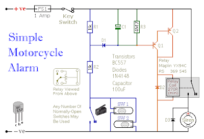
The following circuit is a simple, cheap and easy build motorcycle alarm. The circuit just required 2 transistors to drive the relay the the relay act as a switch to activate the buzzer.
easy build motocycle alarm circuit Schematic with explanation

Any number of normally-open switches may possibly be applied. Fit the mercury switches to ensure that they close when the steering is moved or when the bike is lifted off its side-stand or pushed forward off its centre-stand. Use micro-switches to secure removable panels as well as the lids of panniers and so on. Although at the very leastonce again – the alarm will reset. How lengthy it takes to switch off depends upon the characteristics of the actual parts you have utilized. You are able to adjust the time to suit your requirements by changing the value of C1 and/or R3.

easy build motocycle alarm component

The circuit board and switches need to be protected from the elements. Dampness or condensation will trigger malfunction. With out its terminal blocks – the board is small. Ideally, you need to attempt to locate a siren with sufficient spare space inside to accommodate it. Fit a 1-amp in-line fuse as close as achievable to the power source. This is Extremely Crucial. The fuse is there to secure the wiring – not the circuit board. Rather than utilizing a key-switch you’ll be able to use a hidden switch; or you could use the normally-closed contacts of a tiny relay. Wire the relay coil to ensure that it is energized whilst the ignition is on. Then each and every time you turn the ignition off – the alarm will set itself.

When it is not sounding – the circuit uses practically no present. This need to make it helpful in other circumstances. For instance, powered by dry batteries and using the relay and siren voltages to suit, it might be fitted inside a personal computer or anything else that is in danger of becoming picked up and carried away. The low standby electric current and automatic reset indicates that for this sort of application an external on/off switch might not be essential.

Easy build motorcycle alarm circuit source: www.zen22142.zen.co.uk

Continue reading...

Knight Rider Light Circuit With 6 LEDs

Wednesday, May 29, 2013 | Labels: , , , , , , | 0 comments |
Most of you ask about 6 LED bulbs Knight Rider circuit.So Here it is.You can attach this one for your car or van.Actually this is so attractive circuit.and This circuit operates with 6v.
Continue reading...

Simple Clock pulse Generator with CD4049

Sunday, May 26, 2013 | Labels: , , , , , | 0 comments |
If you want to generate clock with CD4049 CMOS you can do as the follow picture.The typical resister values is 100K and Capacitor is 0.01-0.1uF.The output frequency is about 1/1.1RC ___Hz

Continue reading...

Tiny Subwoofer Amplifier Circuit With UA741

Saturday, April 13, 2013 | Labels: , , , , , | 0 comments |
Sub-woofer circuit for you take it to use together with your sound device or instruments as the tool is small and few digital section. We offers accomplished PCB and part layout.

Mini Subwoofer Top PCB
We use the IC twin operational amplifiers TL072 on this circuit.

This subwoofer project is a subwoofer or a speaker to pressure low frequencies, rank of 20 Hz to a hundred and fifty Hz electronic circuit diagram below shows in details of a circuit and sections of the primary amplifier UA741 for 22 watt in 4 ohm of car subwoofer forcer and that you would be able to activate VR50K for adjusted regularly of mini subwoofer .

The instrument is designed for an existing stereo amplifier, recurrently requires including another blow to the track of riding a subwoofer.
The amplifier makes use of BTL is an effective and low cost ((Bridge Tied Load channels) eight-pin IC UA741 from Philips is now NXP Semiconductors, that may provide a small collection of components and 22W at four ohm load voltage 12 volt car battery default.

Mini Subwoofer Bottom Side

The mini subwoofer consists of a couple of parts: the identify of the potentiometer, dual-linear motion potentiometers, 1/4W resistors, capacitors, electrolytic 25V, 63V Polyester capacitors, 24 W BTL automobile radio RCA audio input amplifier and two speakers four ohm or 8 ohm woofers in isobaric parallel wiring.
Continue reading...

Inverter Overload Protector With Delayed Auto Rest

| Labels: , , , , , , | 0 comments |
An overload condition in an inverter may  permanently  damage  the  power transistor array or burn off the transformer. Some of the domestic inverters sold in the market do not feature an overload shutdown facility, while those incorporating this feature come with a price tag.the circuit presented here is an overload detector which shuts down the inverter  in  an  overload  condition. 

Inverter Overload Protector With Delayed Auto Rest Circuit diagram:

Inverter Overload Protector With Delayed Auto Rest -Circuit -Diagram


It  hasthe following desirable features:
  • It shuts down the inverter and also provides  audio-visual  indication  of  the overload condition.
  • after  shutdown,  it  automatically restarts  the  inverter  with  a  delay  of  6 seconds. thus, it saves the user from the inconvenience  caused  due  to  manually resetting the system or running around in darkness to reset the system at night.
  • It  permanently  shuts  down  the inverter  and  continues  to  give  audio warning,  in  case  there  are  more  than three  successive  overloads.  Under  this condition, the system has to be manually reset.(Successive overload condition indicates that the inverter  output  is  short-circuited or a heavy current is being drawn by the connected load.)
Inverter Overload Protector
Inverter Overload Protector With Delayed Auto Rest

The circuit uses an ammeter  (0-30a)  as  a  transducer  to  detect  overload condition.  Such  an  am-meter  is  generally  present in  almost  all  inverters.  this  ammeter  is connected between the negative supply of the battery and the inverter, as shown in Fig. 2. the voltage developed across this ammeter, due to the flow of current, is very small. It is amplified by IC2, which is wired as a differential amplifier having a gain  of 100. IC3 (NE555) is connected as a Schmitt ‘trigger’, whose output goes low when the voltage at its pin 2 exceeds 3.3V. IC4 (again an NE555 timer) is configured as  a  monostable  multivibrator  with  a pulsewidth of 6 seconds. IC5 (CD4017) is a CMOS counter which counts the three overload  conditions,  after  which  the  sys-tem has to be reset manually, by pressing push-to-on switch S1. the  circuit  can  be  powered  from  the inverter battery. In standby condition, it consumes 8-10 ma of current and around 70 mA with relay (RL1), buzzer (PZ1), and LED1 energised.

Please note the following points carefully:
  • Points A and B at the input of IC2 should be connected to the corresponding points (A and B respectively) across the ammeter.
  • Points C and D on the relay terminals  have  to  be  connected  in  series  with the  already  existing  ‘on’/‘off’  switch  leads of inverter as shown in Fig. 1. this means that one of the two leads terminated on the existing  switch  has  to  be  cut  and  the  cut ends have to be connected to the pole and N/O contacts respectively of relay RL1.
  • The  ammeter  should  be  connected in series with the negative terminal of the battery and inverter, as shown in Fig. 2.Move the wiper of preset VR1 to the extreme position which is grounded. Switch ‘on’ the inverter. For a 300W inverter, connect about 250-260W of load. Now adjust VR1 slowly, until the inverter just trips or shuts down.  repeat the step if necessary. Use good-quality preset with dust cover (e.g. multiturn trimpot) for reliable operation.the circuit can be easily and success-fully installed with minimum modifications to the existing inverter. all the components used are cheap and readily avail-able. the whole circuit can be assembled on a general-purpose PCB. The cost of the whole circuit including relay, buzzer, and PCB does not exceed Rs 100.
Source:  http://www.ecircuitslab.com/2011/11/inverter-overload-protector-with.html


Continue reading...

Control Relay Circuit with 9 Second

Friday, April 12, 2013 | Labels: , , , , , | 0 comments |
See figure below its Control Relay Circuit Schematics.


Control Relay Circuit
Continue reading...