Showing posts with label build. Show all posts

Build a Telephone Record Control Circuit Diagram

Tuesday, September 23, 2014 | Labels: , , , , , , | 0 comments |
This simple Telephone Record Control Circuit Diagram will allow you to connect any tape recorder that has a mic and remote input to a phone line and automatically record both sides of a conversation when ever the phone is in use. You will need to take a couple of voltage readings before connecting the circuit. First determine the polarity of your phone line and connect it to the circuit as shown and then determine the polarity of the remote input and connect it to the circuit.

Circuit operation is as follows. When the phone is on hook the voltage across the phone line is about 48volts dc. When the phone is off hook the voltage will drop to below 10volts dc. When the line voltage is at 48volts the FET is off which causes Q2 and Q3 to be off. When the phone is picked up the FET turns on along with Q2 and Q3 which turns your recorder on. The tape recorder must be in the record mode at all times. As you can see the power source for the circuit is the phone line. 

Telephone Record Control Circuit Diagram

Telephone Record Control Circuit Diagram
 
Continue reading...

Build a18W Car Stereo Amplifier Circuit Diagram

Friday, September 19, 2014 | Labels: , , , , , , | 0 comments |
This automobile stereo amplifier project is a class AB audio power amplifier using the Hitachi HA13118 module. It not only can be used in automobile application but also in any transportable or home amplifier process. It is simple to construct & has a maximum of outside parts. The module has a high power output from a low voltage supply using the bridge tied load system, & a high gain of 55dB.

This project will be useful in applications where the input signal is a low level, without requiring the use of a separate pre-amplifier. This IC module has a built in surge protection circuit, thermal shutdown circuit, ground fault protection circuit & power supply fault protection circuit making it reliable.
The Specifications of this project 
D.C. Input : 8 – 18V at 1-2 A

Power output : 18W maximum, 4 ohm load, 18V DC supply

S/N ratio : > 70 dB

THD : < 0.2% @ 1W

Freq. Response : ~ 30 Hz to 30 kHz, –3 dB

Input level : < 25 mV, for full output (G > 50dB)

Input Impedance : ~ 30 k ohm

The supply voltage necessary for this project is 8 -18V DC, at least one to two Amps. Maximum output power will only be obtained with a power supply of 18V at greater than two A, using a four ohm speaker. The power supply ought to be well filtered to reduce mains hum, a regulated supply will reduce noise even further. Additional filtering is unnecessary if operating from a battery supply.

Circuit Diagram Description

Most of the circuitry is contained within the amplifier module. C10 is the input coupling capacitor and blocks DC from the input. C11 bypasses any RF which may be present at the input. C1 & C2 provide an AC ground for the inverting inputs of the IC. R1/C7 and R2/C8 provide a high frequency load for stability with difficult speakers. C five & C six provide bootstrap feedback for the IC. C9 & C12 provide power supply filtering.

Build a18W Car Stereo Amplifier Circuit Diagram

An externally mounted logarithmic potentiometer of between 10k ohm and 50k ohm, is used depending on the desired input impedance. The impedance ought to be keep as high as feasible for a guitar amp, unless using a separate pre-amp. Make sure-that the heat sink is mounted to the module.


Continue reading...

Build a Wideband UHF Amplifier Circuit Diagram

| Labels: , , , , , , | 0 comments |
This is the simple wide band UHF amplifier with high-performance fetes. The amplifier circuit is designed for 225 MHz center frequency, 1 dB bandwidth of 50 MHz, low input VSWR in a 75-ohm system, and 24 dB gain Three stages of U310 FETs are used in a straight forward design.


Wide-band UHF Amplifier Circuit Diagram


Wideband UHF Amplifier Circuit Diagram

Continue reading...

Build a PC Based Timer Circuit Diagram

| Labels: , , , , , , | 0 comments |
Timers are very useful both for industrial applications and household appliances. Here is a PC-based timer that can be used for controlling the appliances for up to 18 hours. For control, the timer uses a simple program and interface circuit. It is very cost-effective and efficient for those who have a PC at workplace or home. The tolerance is ±1 second.

The circuit for interfacing the PC’s parallel port with the load is very simple. It uses only one IC MCT2E, which isolates the PC and the relay driver circuits. The IC prevents the PC from any short circuit that may occur in the relay driver circuit or appliance. The glowing of LED1 indicates that the appliance is turned on. Transistor BC548 is used as the relay driver.

The program code is written in ‘C’ language and compiled using ‘Turbo C’ compiler. When the program is run, it prompts the user to input the time duration in seconds or minutes to control the appliance. After entering the required timing, press any key from the keyboard.

Suppose you input the total duration as ‘x’ minutes, of which ‘on’ and ‘off’ durations are ‘y’ and ‘z’ minutes, respectively. The program will repeat the on-off cycle for x/(y+z) number of times. After completion of the total time, to repeat the cycle, you will have to reset the time in the program to activate the circuit.

PC-Based Timer Circuit Diagram

PC-Based Timer Circuit Diagram


The program uses two bytes for storing integer type data. So when input is given in terms of seconds or minutes, it can hold 216–1=65,535 seconds or 18 hours at the maximum. The sleep() function in the program is used to hold the appliance in ‘on’ or ‘off’ condition for the ‘on’ and ‘off’ periods as entered by the user against prompts. The sound() function is used to give a beep during ‘on’ condition of the appliance.

EFY note. The source code and executable file of this program have been included in this month’s EFY-CD.

Sourced By: EFY Author Akshy

Continue reading...

Build 32 Watt Amplifier Circuit Using by TDA2050V

| Labels: , , , , , , , | 0 comments |
Build 32 Watt Amplifier Circuit Using by TDA2050V. A 32 Watt per channel stereo power amplifier made using the TDA2050V monolithic integrated circuit.

 32 Watt Amplifier Circuit Diagram


32 Watt Amplifier Circuit Using by TDA2050V


Notes:

This circuit is for a 32 Watt stereo audio power amplifier using the TDA20501. With a dual 22 Volt supply this amplifier can deliver 32W into 8 ohm loudspeakers. Moreover, the TDA 2050 delivers typically 50W music power into 4 ohm load over 1 sec at VS= 22.5V and f = 1KHz. The amplifier is cased as a Pentawatt package see pinout below:


TDA2050V

This is a power amplifier and requires 200mV RMS for full output. Voltage gain is 30.5dB with resistor values shown. Closed loop gain is set by Ratio R1/R2. Increase R2 for less gain and vice versa. Power bandwidth is 20Hz to 80KHz. R3, C3 and R6, C11 form a zobel network to prevent high frequency instability.

The speaker is direct coupled, therefore no expensive large value electrolytics are needed and the bass will be crisp and clean. It is advisable to place fuses in the power supply (not shown).

Parts List:

R1,R4,R5,R8______22k 1/4W Resistor
R2,R7__________680R 1/4W Resistor
R3,R6___________2.2R 1/4W Resistor
C1,C10___________1u NP 25V Capacitor
C2,C12__________22u 63V Electrolytic
C3,C11_________0.47u 400V Polyester
C4,C7,C8,C9_____100n 400V Polyester
C5,C6,C13,C14___220u 63V Electrolytic
U1,U2__________TDA2050V 32W Audio Power Amp
Continue reading...

Build a Power Pulse Using by LM350 and NE555 Circuit Diagram

| Labels: , , , , , , , , , , | 0 comments |
This is a Simple Power Pulse Using by LM350 and NE555 Circuit Diagram. This circuit can use to drive lamp,power LED,DC motor etc. Adjust R5 for output amplitude.Adjust R1 for output power .

Power Pulse Circuit Diagram

Power Pulse Circuit Diagram


The LM350 is adjustable 3-terminal positive voltage regulators is capable of supplying in excess of 3A over a 1.2V to 33V output range.This circuit requires 5-15V power supply.
Continue reading...

Build a Fast Breaker Circuit Diagram

| Labels: , , , , , | 0 comments |
This is the simple and Fast Breaker Circuit Diagram. This 115 Vac, electronic circuit breaker uses the low drive power, low on resistance and fast turn off of the TMOS MTM15N50. The trip point is adjustable, LED fault indication is provided and battery power provides complete circuit isolation. The two `circuit breaker` terminals are across one leg of a full wave diode bridge consisting of D1-D4. Normally, Q1 is turned ON so that the circuit breaker looks like a very low resistance. 

 Fast Electronic Breaker Circuit Diagram


One input to comparator Ul is a fraction of the internal battery voltage and the other input is the drop across zeners D6 and D7 and the voltage drop across R1. If excessive current is drawn, the voltage drop across Rl increases beyond the comparator threshold (determined by the setting of R6), U1 output goes low, Q1 turns OFF, and the circuit breaker `opens.` When this occurs, the LED fault indicator is illuminated.
Continue reading...

Build a 32W Amplifier Circuit Diagram Using by TDA2050V

| Labels: , , , , , , , , | 0 comments |
Build a 32W Amplifier Circuit Diagram Using by TDA2050V. This is a simple circuit diagram, 32w per channel stereo power amplifier made using the TDA2050V monolithic integrated circuit.

32W Amplifier Circuit Diagram 

32W Amplifier Circuit Diagram


Notes:

This circuit is for a 32 Watt stereo audio power amplifier using the TDA20501. With a dual 22 Volt supply this amplifier can deliver 32W into 8 ohm loudspeakers. Moreover, the TDA 2050 delivers typically 50W music power into 4 ohm load over 1 sec at VS= 22.5V and f = 1KHz. The amplifier is cased as a Pentawatt package see pinout below:

TDA2050V

This is a power amplifier and requires 200mV RMS for full output. Voltage gain is 30.5dB with resistor values shown. Closed loop gain is set by Ratio R1/R2. Increase R2 for less gain and vice versa. Power bandwidth is 20Hz to 80KHz. R3, C3 and R6, C11 form a zobel network to prevent high frequency instability.

The speaker is direct coupled, therefore no expensive large value electrolytics are needed and the bass will be crisp and clean. It is advisable to place fuses in the power supply (not shown).

Parts List:

R1,R4,R5,R8______22k 1/4W Resistor
R2,R7__________680R 1/4W Resistor
R3,R6___________2.2R 1/4W Resistor
C1,C10___________1u NP 25V Capacitor
C2,C12__________22u 63V Electrolytic
C3,C11_________0.47u 400V Polyester
C4,C7,C8,C9_____100n 400V Polyester
C5,C6,C13,C14___220u 63V Electrolytic
U1,U2__________TDA2050V 32W Audio Power Amp
Continue reading...

easy build motocycle alarm circuit Schematic with explanation

Wednesday, June 12, 2013 | Labels: , , , , , , , | 0 comments |

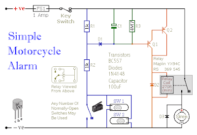
The following circuit is a simple, cheap and easy build motorcycle alarm. The circuit just required 2 transistors to drive the relay the the relay act as a switch to activate the buzzer.

easy build motocycle alarm circuit Schematic with explanation

Any number of normally-open switches may possibly be applied. Fit the mercury switches to ensure that they close when the steering is moved or when the bike is lifted off its side-stand or pushed forward off its centre-stand. Use micro-switches to secure removable panels as well as the lids of panniers and so on. Although at the very leastonce again – the alarm will reset. How lengthy it takes to switch off depends upon the characteristics of the actual parts you have utilized. You are able to adjust the time to suit your requirements by changing the value of C1 and/or R3.

easy build motocycle alarm component

The circuit board and switches need to be protected from the elements. Dampness or condensation will trigger malfunction. With out its terminal blocks – the board is small. Ideally, you need to attempt to locate a siren with sufficient spare space inside to accommodate it. Fit a 1-amp in-line fuse as close as achievable to the power source. This is Extremely Crucial. The fuse is there to secure the wiring – not the circuit board. Rather than utilizing a key-switch you’ll be able to use a hidden switch; or you could use the normally-closed contacts of a tiny relay. Wire the relay coil to ensure that it is energized whilst the ignition is on. Then each and every time you turn the ignition off – the alarm will set itself.

When it is not sounding – the circuit uses practically no present. This need to make it helpful in other circumstances. For instance, powered by dry batteries and using the relay and siren voltages to suit, it might be fitted inside a personal computer or anything else that is in danger of becoming picked up and carried away. The low standby electric current and automatic reset indicates that for this sort of application an external on/off switch might not be essential.

Easy build motorcycle alarm circuit source: www.zen22142.zen.co.uk

Continue reading...