Showing posts with label amplifier. Show all posts

Simple 50W Electronic Amplifier Circuit Diagram

Friday, September 26, 2014 | Labels: , , , , , | 0 comments |
This Simple 50W Electronic Amplifier Circuit Diagram project is an IC amplifier module from ST Microelectronics, the TDA7294. It is intended for use as a top quality audio class AB amplifier in hi-fi applications. Its low noise and distortion, wide bandwidth and nice output current capability, enabling it to supply high power in to both four ohm and 8 ohm lots. Its both short circuit and thermal protection.

With the addition of a handful of parts and an appropriate power supply, this module will deliver over 50W RMS in to four or 8 ohms-with < 0.1% Total Harmonic Distortion (THD) and < 0.1% Inter-modulation Distortion (IMD). It is also suitable as a replacement power amp stage, or upgrade for plenty of existing amplifiers of between 30W-50W, provided they have an appropriate dual supply, & most do.

The Specifications of the electronic amplifier project there are:

D.C. Input : 35V
Output power : > 50W RMS, 4-8 ohm load.
Gain : 24 dB (30dB modification)
Input sensitivity : one.3V for 50W, 8 ohm
Signal-to-Noise ratio : > 95 dB, (>105 dBA)
Frequency response : approx. 20Hz - 200kHz, �3 dB
Slew rate : > 10V/uS
THD : < 0.01%, 1W-40W, 1kHz
IMD : < 0.01%, 1W

The maximum supply voltage of the IC is +/- 40V. However the maximum dissipation of the IC can be exceeded even at a lower voltage. Therefore the supply voltage used require not be over +/- 35V. This can be constructed using a 50V middle tapped-transformer, a diode bridge rated at 5A (min.) & a pair of electrolytic capacitors, as shown below. A lower secondary voltage transformer could even be used but the reduced DC voltage will lead to less power output in to 8 ohms. You can still receive 50W in to four ohms with only 24V supply rails.

A 36V C.T. transformer will give you approx +/- 25V rails. The-mains transformer used ought to be rated at a maximum of 80VA. In the event you require to run modules in a stereo amplifier you can use a common power supply. In this case the transformer ought to be rated at 150VA or greater.

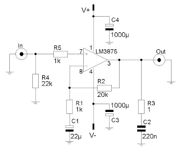
Electronic Amplifier Circuit Diagram Description

Most of the circuitry is contained within the IC module. The input signal is applied to pin three by capacitor C1 & low-pass filter R1/C2. The filter improves the pulse response & helps cease RF signals. The lower -3dB point is determined-by R2/C1 & R4/C3. This is about 20Hz for the values used. The upper -3dB point is over 200kHz. C7/C8 & C9/C10 provide additional power supply filtering or decoupling.

Simple 50W Electronic Amplifier Circuit Diagram


R3/R4 are the feedback resistors. The gain is 1+R3/R4 which is approx 16 times, or 24dB. In case you need to increase the input sensitivity you may alter the resistors to suit. Changing R3 to 22k would increase the gain to 30dB and lower the input-required for 50W in to 8 ohm, to 0.6V, without affecting performance much. In case you reduce the worth of R4 you will also need to increase C3 to maintain bass response, as this sets the feedback low frequency roll off.

Pin ten is a mute input and pin 9 provides a standby mode. Muting ought to always happen before standby mode is selected. Connecting these pins permanently to the supply rail ensures that the amplifier comes on immediately on power up. Any switch-on clicks may be eliminated by increasing the time constants of R5/C4 and R6/C5 if necessary.

Make definite that a heavy duty heat-sink rated at least one.4 degree C/W or better is used.

Simple 50W Electronic Amplifier Circuit Diagram

Continue reading...

Mini10 W Audio Amplifier

| Labels: , , , | 0 comments |
This design is based on the 18 Watt Audio Amplifier, and was developed mainly to satisfy the requests of correspondents unable to locate the TLE2141C chip. It uses the widespread NE5532 Dual IC but, obviously, its power output will be comprised in the 9.5 - 11.5W range, as the supply rails cannot exceed ±18V.

10 W Audio Amplifier Circuit Diagram

10 W Audio Amplifier Circuit Diagram


As amplifiers of this kind are frequently used to drive small loudspeaker cabinets, the bass frequency range is rather sacrificed. Therefore a bass-boost control was inserted in the feedback loop of the amplifier, in order to overcome this problem without quality losses. The bass lift curve can reach a maximum of +16.4dB @ 50Hz. In any case, even when the bass control is rotated fully counterclockwise, the amplifier frequency response shows a gentle raising curve: +0.8dB @ 400Hz, +4.7dB @ 100Hz and +6dB @ 50Hz (referred to 1KHz).

Notes:

  • Can be directly connected to CD players, tuners and tape recorders.
  • Schematic shows left channel only, but C3, C4, IC1 and the power supply are common to both channels.
  • Numbers in parentheses show IC1 right channel pin connections.
  • A log type for P2 will ensure a more linear regulation of bass-boost.
  • Do not exceed 18 + 18V supply.
  • Q3 and Q4 must be mounted on heatsink.
  • D1 must be in thermal contact with Q1.
  • Quiescent current (best measured with an Avo-meter in series with Q3 Emitter) is not critical.
  • Set the volume control to the minimum and R3 to its minimum resistance.
  • Power-on the circuit and adjust R3 to read a current drawing of about 20 to 25mA.
  • Wait about 15 minutes, watch if the current is varying and readjust if necessary.
  • A correct grounding is very important to eliminate hum and ground loops. Connect to the same point the ground sides of J1, P1, C2, C3 &C4. Connect C9 to the output ground.
  • Then connect separately the input and output grounds to the power supply ground.

Parts:

P1_________________22K   Log.Potentiometer (Dual-gang for stereo)
P2________________100K Log.Potentiometer (Dual-gang for stereo)
R1________________820R 1/4W Resistor
R2,R4,R8____________4K7 1/4W Resistors
R3________________500R 1/2W Trimmer Cermet
R5_________________82K 1/4W Resistor
R6,R7______________47K 1/4W Resistors
R9_________________10R 1/2W Resistor
R10__________________R22 4W Resistor (wirewound)

C1,C8_____________470nF 63V Polyester Capacitor
C2,C5_____________100µF 25V Electrolytic Capacitors
C3,C4_____________470µF 25V Electrolytic Capacitors
C6_________________47pF 63V Ceramic or Polystyrene Capacitor
C7_________________10nF 63V Polyester Capacitor
C9________________100nF 63V Polyester Capacitor

D1______________1N4148 75V 150mA Diode

IC1_____________NE5532 Low noise Dual Op-amp

Q1_______________BC547B 45V 100mA NPN Transistor
Q2_______________BC557B 45V 100mA PNP Transistor
Q3_______________TIP42A 60V 6A PNP Transistor
Q4_______________TIP41A 60V 6A NPN Transistor

J1__________________RCA audio input socket

Power supply parts:

R11_________________1K5  1/4W Resistor

C10,C11__________4700µF 25V Electrolytic Capacitors

D2________________100V 4A Diode bridge
D3________________5mm. Red LED

T1________________220V Primary, 12 + 12V Secondary 24-30VA Mains transformer

PL1_______________Male Mains plug

SW1_______________SPST Mains switch
 

Technical data:

Output power:
10 Watt RMS into 8 Ohm (1KHz sinewave)
Sensitivity:
115 to 180mV input for 10W output (depending on P2 control position)
Frequency response:
See Comments above
Total harmonic distortion @ 1KHz:
0.1W 0.009% 1W 0.004% 10W 0.005%
Total harmonic distortion @ 100Hz:
0.1W 0.009% 1W 0.007% 10W 0.012%
Total harmonic distortion @ 10KHz:
0.1W 0.056% 1W 0.01% 10W 0.018%
Total harmonic distortion @ 100Hz and full boost:
1W 0.015% 10W 0.03%
Max. bass-boost referred to 1KHz:
400Hz = +5dB; 200Hz = +7.3dB; 100Hz = +12dB; 50Hz = +16.4dB; 30Hz = +13.3dB
Unconditionally stable on capacitive loads
 
Continue reading...

Crystal cMoy Freeform Headphone Amplifier

Tuesday, September 23, 2014 | Labels: , , , , | 0 comments |
Well the time has come to pour the clear casting resin .I have say I have been putting this off for some time ,but it all turned out well in the end as you can see below :) [Link]

Stunning Crystal cMoy Freeform Headphone Amplifier
Continue reading...

Build a18W Car Stereo Amplifier Circuit Diagram

Friday, September 19, 2014 | Labels: , , , , , , | 0 comments |
This automobile stereo amplifier project is a class AB audio power amplifier using the Hitachi HA13118 module. It not only can be used in automobile application but also in any transportable or home amplifier process. It is simple to construct & has a maximum of outside parts. The module has a high power output from a low voltage supply using the bridge tied load system, & a high gain of 55dB.

This project will be useful in applications where the input signal is a low level, without requiring the use of a separate pre-amplifier. This IC module has a built in surge protection circuit, thermal shutdown circuit, ground fault protection circuit & power supply fault protection circuit making it reliable.
The Specifications of this project 
D.C. Input : 8 – 18V at 1-2 A

Power output : 18W maximum, 4 ohm load, 18V DC supply

S/N ratio : > 70 dB

THD : < 0.2% @ 1W

Freq. Response : ~ 30 Hz to 30 kHz, –3 dB

Input level : < 25 mV, for full output (G > 50dB)

Input Impedance : ~ 30 k ohm

The supply voltage necessary for this project is 8 -18V DC, at least one to two Amps. Maximum output power will only be obtained with a power supply of 18V at greater than two A, using a four ohm speaker. The power supply ought to be well filtered to reduce mains hum, a regulated supply will reduce noise even further. Additional filtering is unnecessary if operating from a battery supply.

Circuit Diagram Description

Most of the circuitry is contained within the amplifier module. C10 is the input coupling capacitor and blocks DC from the input. C11 bypasses any RF which may be present at the input. C1 & C2 provide an AC ground for the inverting inputs of the IC. R1/C7 and R2/C8 provide a high frequency load for stability with difficult speakers. C five & C six provide bootstrap feedback for the IC. C9 & C12 provide power supply filtering.

Build a18W Car Stereo Amplifier Circuit Diagram

An externally mounted logarithmic potentiometer of between 10k ohm and 50k ohm, is used depending on the desired input impedance. The impedance ought to be keep as high as feasible for a guitar amp, unless using a separate pre-amp. Make sure-that the heat sink is mounted to the module.


Continue reading...

Build a Wideband UHF Amplifier Circuit Diagram

| Labels: , , , , , , | 0 comments |
This is the simple wide band UHF amplifier with high-performance fetes. The amplifier circuit is designed for 225 MHz center frequency, 1 dB bandwidth of 50 MHz, low input VSWR in a 75-ohm system, and 24 dB gain Three stages of U310 FETs are used in a straight forward design.


Wide-band UHF Amplifier Circuit Diagram


Wideband UHF Amplifier Circuit Diagram

Continue reading...

Build 32 Watt Amplifier Circuit Using by TDA2050V

| Labels: , , , , , , , | 0 comments |
Build 32 Watt Amplifier Circuit Using by TDA2050V. A 32 Watt per channel stereo power amplifier made using the TDA2050V monolithic integrated circuit.

 32 Watt Amplifier Circuit Diagram


32 Watt Amplifier Circuit Using by TDA2050V


Notes:

This circuit is for a 32 Watt stereo audio power amplifier using the TDA20501. With a dual 22 Volt supply this amplifier can deliver 32W into 8 ohm loudspeakers. Moreover, the TDA 2050 delivers typically 50W music power into 4 ohm load over 1 sec at VS= 22.5V and f = 1KHz. The amplifier is cased as a Pentawatt package see pinout below:


TDA2050V

This is a power amplifier and requires 200mV RMS for full output. Voltage gain is 30.5dB with resistor values shown. Closed loop gain is set by Ratio R1/R2. Increase R2 for less gain and vice versa. Power bandwidth is 20Hz to 80KHz. R3, C3 and R6, C11 form a zobel network to prevent high frequency instability.

The speaker is direct coupled, therefore no expensive large value electrolytics are needed and the bass will be crisp and clean. It is advisable to place fuses in the power supply (not shown).

Parts List:

R1,R4,R5,R8______22k 1/4W Resistor
R2,R7__________680R 1/4W Resistor
R3,R6___________2.2R 1/4W Resistor
C1,C10___________1u NP 25V Capacitor
C2,C12__________22u 63V Electrolytic
C3,C11_________0.47u 400V Polyester
C4,C7,C8,C9_____100n 400V Polyester
C5,C6,C13,C14___220u 63V Electrolytic
U1,U2__________TDA2050V 32W Audio Power Amp
Continue reading...

Simple 25W Audio Power Amplifier Circuit

| Labels: , , , , , | 0 comments |
This audio power amplifier project is based on LM1875 amplifier module from National Semiconductor. It can deliver up to 30W of power using an 8 ohm load & dual 30V DC power supplies. It is designed to operate with maximum outside parts with current limit & thermal shutdown protection features . Other features include high gain, quick slew rate, wide power supply range, giant output voltage swing & high current capability.

Summary of the audio amply-fire features:

  • Low distortion: 0.015%, 1 kHz, 20 W
  • Wide power bandwidth: 70 kHz
  • Wide supply range 16V-60V
  • Up to 30 watts output power
  • Internal output protection diodes
  • Protection for AC & DC short circuits to ground
  • 94 dB ripple rejection
  • Plastic power package TO-220
25V Power Supply

The schematic below shows how the +25V DC & -25V DC are obtained. In order to provide power supply for two stereo amplifiers, a power transformer rating of 80VA with 240V/36V middle tapped secondary winding is used. The secondary output of the transformer is rectified by using 1N5401 diodes together with four electrolytic capacitors to smoother the ripple voltage. A fuse & a varistor are connected at the primary input to protect the circuit against power surge.


Audio Amplifier Module

The +25V & -25V DC power supply are connected to the audio amplifier module through a 2A fuse with the peripheral devices shown in the schematic below. The audio input signal to be amplified is coupled to pin one of LM1875 through the resistor R1 and electrolytic capacitor E5.

The output signal at pin four of LM1875 can be used to directly drive a 8 ohm loudspeaker. Resistor R6 and capacitor C5 prevent-the capacitance developed at the long speaker leads from driving the amplifier in to High Frequency Oscillation.

A heat-sink with a thermal resistance rating of one.4 Cecilius/Watt or better must be used or else the amplifier module will-be cut-off from operation due to the heat that will build up in the coursework of the operation of the amplifier. Take note that the heat sink tab on the IC module is internally connected to the -25V power supply hence it must be isolated from the heat sink by the use of an insulating washer. If this is not done, the negative rail will be shorted to ground.


Sourced By: Streampowers.blogspot.com
Continue reading...

Build a 32W Amplifier Circuit Diagram Using by TDA2050V

| Labels: , , , , , , , , | 0 comments |
Build a 32W Amplifier Circuit Diagram Using by TDA2050V. This is a simple circuit diagram, 32w per channel stereo power amplifier made using the TDA2050V monolithic integrated circuit.

32W Amplifier Circuit Diagram 

32W Amplifier Circuit Diagram


Notes:

This circuit is for a 32 Watt stereo audio power amplifier using the TDA20501. With a dual 22 Volt supply this amplifier can deliver 32W into 8 ohm loudspeakers. Moreover, the TDA 2050 delivers typically 50W music power into 4 ohm load over 1 sec at VS= 22.5V and f = 1KHz. The amplifier is cased as a Pentawatt package see pinout below:

TDA2050V

This is a power amplifier and requires 200mV RMS for full output. Voltage gain is 30.5dB with resistor values shown. Closed loop gain is set by Ratio R1/R2. Increase R2 for less gain and vice versa. Power bandwidth is 20Hz to 80KHz. R3, C3 and R6, C11 form a zobel network to prevent high frequency instability.

The speaker is direct coupled, therefore no expensive large value electrolytics are needed and the bass will be crisp and clean. It is advisable to place fuses in the power supply (not shown).

Parts List:

R1,R4,R5,R8______22k 1/4W Resistor
R2,R7__________680R 1/4W Resistor
R3,R6___________2.2R 1/4W Resistor
C1,C10___________1u NP 25V Capacitor
C2,C12__________22u 63V Electrolytic
C3,C11_________0.47u 400V Polyester
C4,C7,C8,C9_____100n 400V Polyester
C5,C6,C13,C14___220u 63V Electrolytic
U1,U2__________TDA2050V 32W Audio Power Amp
Continue reading...

20W 12V Compact High Performance Stereo Amplifier

Wednesday, June 12, 2013 | Labels: , , , , , , | 0 comments |
Amplifiers which run from 12V DC generally don’t put out much power and they are usually not hifi as well. But this little stereo amplifier ticks the power and low distortion boxes. With a 14.4V supply, it will deliver 20 watts per channel into 4-ohm loads at clipping while harmonic distortion at lower power levels is typically less than 0.03%.

This is an ideal project for anyone wanting a compact stereo amplifier that can run from a 12V battery. It could be just the ticket for buskers who want a small but gutsy amplifier which will run from an SLA battery or it could used anywhere that 12V DC is available – in cars, recreational vehicles, remote houses with 12V DC power or where ever.

12 Volt 20W Stereo Amplifier circuit schematic
20W Stereo Audio Amplifier

Because it runs from DC, it will be an ideal beginner’s or schoolie’s project, with no 240VAC power supply to worry about. You can run it from a 12V battery or a DC plugpack. But while it may be compact and simple to build, there is no need to apologise for “just average” performance. In listening tests from a range of compact discs, we were very impressed with the sound quality.

Long-time readers might recall that we presented a similar 12V power amplifier design back in May 2001. It was a similar configuration to this one but it is now completely over-shadowed by the much lower distortion and greatly improved signal-to-noise ratio of this new design. In fact, let’s be honest: the previous unit is not a patch on this new design. It used two TDA1519A ICs which resulted in distortion figures above 1% virtually across the board and a signal-to-noise ratio of only -69dB unweighted.

20W Stereo Amplifier circuit schematic
20W Stereo Amplifier Circuit

However, by using the TDA­7377 power amplifier IC and making some other improvements, the THD (total harmonic distortion) of the new design is about 50 times better than the older unit (see performance graphs for details). The bottom line is that the THD under typical conditions is around just 0.03% or less. It is also able to deliver more output power due to the improved output transistors in the new power amplifier IC.

In addition, its idle power consumption is low – not much more than 1W. As a result, if you don’t push it too hard it will run cool and won’t drain the battery too quickly. And because the IC has self-protection circuitry, it’s just about indestructible. It will self-limit or shut down if it overheats and the outputs are deactivated if they are shorted.

Circuit diagram:
12V 20W Stereo Amplifier circuit schematic
20W Stereo Amplifier Circuit Diagram

With a 12V supply, the largest voltage swing a conventional solid-state power amplifier can generate is ±6V. This results in a meagre 4.5W RMS into 4O and 2.25W RMS into 8O, without considering losses in the output transistors. Even if the DC supply is around 14.4V (the maximum that can normally be expected from a 12V car battery), that only brings the power figures up to 6.48W and 3.24W for 4O and 8O loads respectively – still not really enough.

There are three common solutions to this problem. The first is to boost the supply voltage using a switchmode DC converter. This greatly increases the cost and complexity of the amplifier but it is one way of getting a lot of power from a 12V supply. However, we wanted to keep this project simple and that rules out this technique.

Parts layout:
PCB layout of compact 12V 20W Stereo Amplifier circuit schematic

There are variations on the boosting method, such as the class H architecture used in the TDA1562Q IC featured in the Portapal PA Amplifier (SILICON CHIP, February 2003). It is able to achieve 40W/channel but with >0.1% THD. In that case, the amplifier output itself provides the switching for a charge pump. The second method is to lower the speaker impedance. Some car speakers have an impedance as low as 2O, which allows twice as much power to be delivered at the same supply voltage. However, we don’t want to restrict this amplifier to 2O loudspeakers.
Author: Nicholas Vinen - Copyright: Silicon Chip
Continue reading...

LM3875 High Audio Amplifier 56W

Friday, May 17, 2013 | Labels: , , , , | 0 comments |
LM3875-High Audio Amplifier 56W
The LM3875 is an audio amplifier for high power output capable of delivering 56W of continuous average power to a load 8. The performance of the LM3875, utilizing its maximum instantaneous auto temperature (° Ke) (Spike ™) protection circuitry, places it in a class above discrete and hybrid amplifiers by providing a yes, dynamically protected area of safe operation (SOA). SPIKE protection means that these parts are fully protected against output overvoltage, voltage surges caused by shorts to the supplies, the peak temperature thermal runaway, and instantaneous.

This amplifier circuit is based on the non-inverted GainClone standard configuration. I did some calucaltions the feedback resistor and other components in order to check the gain, etc. For more background on the calculations relevant to GainClones in the background section.

LM3875-High Audio Amplifier 56WParameters IC LM3875

Output Current 6000 mA.
Offset Voltage max, 25C 10 mV.
Gain Bandwidth 8 MHz.
Supply Min 20 Volt.
Supply Max 84 Volt.
Supply Current Per Channel 30 mA.
PowerWise Rating 2 3750 uA/MHz.
Slew Rate 11 Volts/usec.
Input OutputType Not Rail to Rail.
Max Input Bias Current 1000 nA.
Special Features AvCl>10.
Function Op Amp.
Channels 1 Channels.
Temperature Min 0 deg C.
Temperature Max 70 deg C.
Continue reading...

Tiny Subwoofer Amplifier Circuit With UA741

Saturday, April 13, 2013 | Labels: , , , , , | 0 comments |
Sub-woofer circuit for you take it to use together with your sound device or instruments as the tool is small and few digital section. We offers accomplished PCB and part layout.

Mini Subwoofer Top PCB
We use the IC twin operational amplifiers TL072 on this circuit.

This subwoofer project is a subwoofer or a speaker to pressure low frequencies, rank of 20 Hz to a hundred and fifty Hz electronic circuit diagram below shows in details of a circuit and sections of the primary amplifier UA741 for 22 watt in 4 ohm of car subwoofer forcer and that you would be able to activate VR50K for adjusted regularly of mini subwoofer .

The instrument is designed for an existing stereo amplifier, recurrently requires including another blow to the track of riding a subwoofer.
The amplifier makes use of BTL is an effective and low cost ((Bridge Tied Load channels) eight-pin IC UA741 from Philips is now NXP Semiconductors, that may provide a small collection of components and 22W at four ohm load voltage 12 volt car battery default.

Mini Subwoofer Bottom Side

The mini subwoofer consists of a couple of parts: the identify of the potentiometer, dual-linear motion potentiometers, 1/4W resistors, capacitors, electrolytic 25V, 63V Polyester capacitors, 24 W BTL automobile radio RCA audio input amplifier and two speakers four ohm or 8 ohm woofers in isobaric parallel wiring.
Continue reading...

25W Audio Power Amplifier Rise

Friday, April 12, 2013 | Labels: , , , , | 0 comments |
This audio energy amplifier undertaking is based on LM1875 amplifier module from National Semiconductor. It can deliver as so much as 30W of energy the utilization of an 8 ohm load & twin 30V DC power provides. It is designed to operate with most outdoor parts with current limit & thermal shutdown protection features . Other features include high achieve, fast slew charge, huge energy provide vary, giant output voltage swing & high present functionality.

Summary of the audio amply-fire options:

  • Low distortion: 0.015%, 1 kHz, 20 W
  • Wide power bandwidth: 70 kHz
  • Wide supply range 16V-60V
  • Up to 30 watts output energy
  • Internal output safety diodes
  • Protection for AC & DC brief circuits to floor
  • 94 dB ripple rejection
  • Plastic energy bundle TO-220
25V Power Supply

The schematic beneath shows how the +25V DC & -25V DC are acquired. In order to provide power provide for two stereo amplifiers, a power transformer score of 80VA with 240V/36V middle tapped secondary winding is used. The secondary output of the transformer is rectified by using 1N5401 diodes along side four electrolytic capacitors to smoother the ripple voltage. A fuse & a varistor are related at the major enter to give protection to the circuit once morest energy surge.


Audio Amplifier Module

The +25V & -25V DC power provide are related to the audio amplifier module thru a 2A fuse with the peripheral tools shown in the schematic under. The audio enter signal to be amplified is coupled to pin one among LM1875 throughout the resistor R1 and electrolytic capacitor E5.

The output sign at pin four of LM1875 can be utilized to immediately drive a eight ohm loudspeaker. Resistor R6 and capacitor C5 prevent-the capacitance developed on the lengthy speaker leads from riding the amplifier in to High Frequency Oscillation.

A heat-sink with a thermal resistance ranking of one.4 Cecilius/Watt or better should be used or else the amplifier module will-be cut-off from operation because of the heat in an effort to build up in the directionwork of the operation of the amplifier. Take note that the warmth sink tab on the IC module is internally related to the -25V power supply hence it must be remoted from the warmth sink by the use of an insulating washer. If this isn't finished, the negative rail shall be briefed to ground.


Continue reading...

RF Fm 88 108 MHz 20W amplifier

Thursday, April 11, 2013 | Labels: , , , , , , | 0 comments |
This Fm rf power amplifier has 2 transistors from Philips : BLV 10 and BLW 87. The 2 rf transistors work in class C and this fm amplifier has a total gain of 21dB ( 100 X ) and efficiency 55 – 65%.
One low pass filter with 9 components ensures 60dB rejection on the second harmonic. There is no need for tune-up to cover the whole 88 – 108 MHz FM frequencies.


source [link] 
Continue reading...