Friday, September 26, 2014
|
Labels:
aircraft,
fm,
receiver,
simple,
vhf
|
|
VHF FM Aircraft Receiver is a supererogation receiver developed for listening to FM transmitters but also tunes the aircraft band and the top portion of the FM broadcast band. Receives both AM and FM (107mHz to 135 MHz). You can use this receiver with the any FM transmitter. The receiver is amazingly simple using only one transistor for the receiver section and one IC for the audio section. This circuit is a self-quenching regenerative RF receiver also known as a super regenerative receiver. A superregenerative receiver performs two basic functions.
First it feeds back a portion of the received signal from it’s output in phase to its input; and second a super audible quenching oscillator drives the amplifier through the point of oscillation and maximum sensitivity and then quenches the oscillation repeatedly. This keeps the feedback from driving the circuit into self-oscillation and allows the signal to be regenerated over and over again. In this version of the circuit, both functions are performed by the circuitry associated with Q1. The rest of the circuit, shown to the right of L3 in the schematic, comprise the audio amplification circuit and are centered on the LM386 Audio Amp IC. In this configuration the LM386 is set at a gain of 200 and feeds it’s output to a standard 1/8-inch diameter stereo phone jack. The audio can then be heard by plugging any standard stereo headset into the jack.
Tuesday, May 28, 2013
|
Labels:
200m,
fm,
transmitter
|
|
This is a Fm Transmitter circuit.This circuit can Transmit signals up to 200M.L1 is 1mH inductor.When I built this circuit I used PCB.

Note
# Make inductor with the support of this formular L = (d²n²) / (18d+40l)
L is the inductance of the coil in uH
d is the coil diameter in inches
l is the coil length in inches
n is the number of turns
# Use 12V power supply for this circuit.
# Build this circuit on a PCB
Monday, May 13, 2013
|
Labels:
adaptor,
car,
circuit,
fm,
for,
stereo
|
|
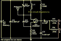
With this compact FM adapter circuit plugged into the audio out of your cassete player or i Pod out put,you can listen your favorite music on your car stereo.This circuit is very useful if your car stereo does not have an auxiliary in socket.The circuit is nothing buy an short range FM transmitter.The FM transmitter circuit is based on low power NPN transistor 2N2222.The tank circuit consisting of L1 & C1 produces the necessary oscillations at the collector of Q1.The capacitance C4 , resistance R3 & R4 performs the function of mixing the stereo out put from the audio player or i-Pod.The emitter resistance R2 provides sufficient stability to the circuit.It also limits the collector current to increase the battery life.
Notes.
* Use a 28SWG , 10 cm insulated copper wire as antenna.
* For L1.make 8 turns of 20 SWG insulated copper wire on a 5mm dia plastic former.
* Power the circuit from a 3V battery.
* Assemble the circuit on a good quality PCB or common board.
* C1 can be a 50pF trimmer.
|
Labels:
fm,
transmitter,
versatile
|
|
Here is the circuit diagram of a versatile FM transmitter that doesn’t have a coil. The circuit is simple and easy to assemble.
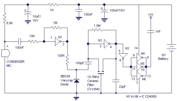
The gate N1 acts as a buffer for strengthening the signals from the condenser microphone. The inverter N2 with its associated components forms a radio frequency oscillator in the FM region.The varicap diode BB109 is used for frequency modulating the audio signal to the carrier wave generated by the oscillator.Inverters N4 t0 N6 are used to drive the antenna.As the N4,N5,N6 are connected in parallel their effective output impedance is very less and can easily drive the antenna.
Notes.
* All electrolytic capacitors must be rated 10V.
* Use any general purpose condenser microphone.You can easily get one from old telephone or tape recorder.
* Use a 10 cm long wire as antenna.
* Gates N1 to N6 belong to same IC CD4069.
* The battery can be a 9V transistor radio battery.Adapters are not recommended because they would induce noise in the circuit.
Continue reading...


