Showing posts with label for. Show all posts

An LCD Clock Kit Suitable for Beginners with Open Source Arduino Firmware

Friday, September 19, 2014 | Labels: , , , , , , , , , , , | 0 comments |
Simpleclock is an easy to assemble attractive 4-digit 7-segment LED display clock with temperature and alarm function. It is available in three display colors: Red, Blue and White. It comes as a kit of through-the-hole parts and can be soldered by any person with basic soldering experience. An attractive acrylic stand is included. [Link]

Continue reading...

Robot Shield for Arduino

| Labels: , , , | 0 comments |
The idea behind this post is to bring together some robot designs and transform them in a new device with new hardware and standard software (arduino of course) and so easier to use.  These robots have three things in common: a mechanical structure, the hardware and the software. While the mechanical part is necessarily different.

Robot Shield for Arduino
We wanted to understand if there was a hardware board that could be common, with a unique development system. The choice, quite obviously, has the Arduino board, which with its development environment is perfect to create similar projects.
Continue reading...

Dual Polarity Unregulated PSU For High End Audio Amps

Wednesday, May 29, 2013 | Labels: , , , , , , , , | 0 comments |
A power supply suitable for use with the hi-fi amplifiers presented in the predeeding project is perfectly simple, and no great skill is required to build (or design) one. There are a few things one should be careful with, such as the routing of high current leads, but these are easily accomplished. Design of this power supply is very simple. A 4 ampere fuse is used to protect the transformer and two LEDs at the end of this circuit are used to indicate power state On and Off. At the ouptut there are 6 capacitors used you can reduce the quantity of these filter capacitors to 2 or according to your own choice.

click on the images to enlarge
Continue reading...

FM adaptor circuit for car stereo

Monday, May 13, 2013 | Labels: , , , , , | 0 comments |

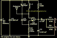
With this compact FM adapter circuit plugged into the audio out of your cassete player or i Pod out put,you can listen your favorite music on your car stereo.This circuit is very useful if your car stereo does not have an auxiliary in socket.The circuit is nothing buy an short range FM transmitter.The FM transmitter circuit is based on low power NPN transistor 2N2222.The tank circuit consisting of L1 & C1 produces the necessary oscillations at the collector of Q1.The capacitance C4 , resistance R3 & R4 performs the function of mixing the stereo out put from the audio player or i-Pod.The emitter resistance R2 provides sufficient stability to the circuit.It also limits the collector current to increase the battery life.

Notes.

* Use a 28SWG , 10 cm insulated copper wire as antenna.
* For L1.make 8 turns of 20 SWG insulated copper wire on a 5mm dia plastic former.
* Power the circuit from a 3V battery.
* Assemble the circuit on a good quality PCB or common board.
* C1 can be a 50pF trimmer.
Continue reading...

Extend Timer Range For The 555

Wednesday, April 17, 2013 | Labels: , , , , , | 0 comments |
Anyone who has designed circuits using the 555 timer chip will, at some time have wished that it may be programmed for longer timing periods. Timing lengths larger than a couple of minutes are tough to succeed in as a outcome of part leakage currents in massive timing capacitors change into vital. There is then again no reason to opt for a basically digital resolution just yet. The circuit shown here uses a 555 timer in the design but nonetheless achieves a timing interval of as much as an hour! The trick right here is to feed the timing capacitor now not with a constant voltage but with a pulsed dc voltage. The pulses are derived from the un smoothed low voltage output of the facility provide bridge rectifier.

The power provide output is just now not referenced to earth potential and the pulsing full wave rectified sign is fed to the bottom of T1 by the use of resistor R1. A 100-Hz sq. wave signal is produced on the collector of T1 as the transistor switches. The positive 1 of 2 of this waveform charges up the timing capacitor C1 by manner of D2 and P1. Diode D2 forestalls the cost on C1 from discharging through T1 when the sq. wave signal goes low. Push-button S1 is used to start the timing duration. This methodology of charging uses moderately low component worths for P1 (2.2 MΩ) and C1 (100 to 200 µF) however succeed ins timing periods of as much as an hour which is much longer than a regular 555 circuit configuration.

Continue reading...