Showing posts with label schematic. Show all posts

latest Door Knob Touch Alarm circuit schematic with explanation

Wednesday, June 12, 2013 | Labels: , , , , , , , , | 0 comments |
Door Knob Touch Alarm circuit diagram

This is door knob touch alarm for your home security purpose. The alarm will be activated when someone touch the metal door knod. This circuit won’t work on full metal door.


Download the schematic drawing

Continue reading...

easy build motocycle alarm circuit Schematic with explanation

| Labels: , , , , , , , | 0 comments |

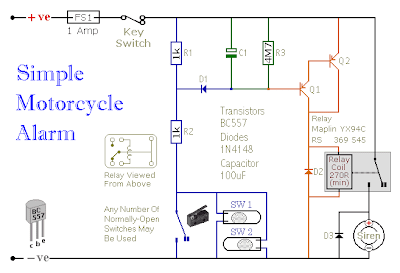
The following circuit is a simple, cheap and easy build motorcycle alarm. The circuit just required 2 transistors to drive the relay the the relay act as a switch to activate the buzzer.

easy build motocycle alarm circuit Schematic with explanation

Any number of normally-open switches may possibly be applied. Fit the mercury switches to ensure that they close when the steering is moved or when the bike is lifted off its side-stand or pushed forward off its centre-stand. Use micro-switches to secure removable panels as well as the lids of panniers and so on. Although at the very leastonce again – the alarm will reset. How lengthy it takes to switch off depends upon the characteristics of the actual parts you have utilized. You are able to adjust the time to suit your requirements by changing the value of C1 and/or R3.

easy build motocycle alarm component

The circuit board and switches need to be protected from the elements. Dampness or condensation will trigger malfunction. With out its terminal blocks – the board is small. Ideally, you need to attempt to locate a siren with sufficient spare space inside to accommodate it. Fit a 1-amp in-line fuse as close as achievable to the power source. This is Extremely Crucial. The fuse is there to secure the wiring – not the circuit board. Rather than utilizing a key-switch you’ll be able to use a hidden switch; or you could use the normally-closed contacts of a tiny relay. Wire the relay coil to ensure that it is energized whilst the ignition is on. Then each and every time you turn the ignition off – the alarm will set itself.

When it is not sounding – the circuit uses practically no present. This need to make it helpful in other circumstances. For instance, powered by dry batteries and using the relay and siren voltages to suit, it might be fitted inside a personal computer or anything else that is in danger of becoming picked up and carried away. The low standby electric current and automatic reset indicates that for this sort of application an external on/off switch might not be essential.

Easy build motorcycle alarm circuit source: www.zen22142.zen.co.uk

Continue reading...

Audi Electric Mirror Wiring Diagramcircuit Schematic

Friday, May 31, 2013 | Labels: , , , , , | 0 comments |
Headlight Wiring Diagram on Download The 1997 Ford Contour Headlight Schematic And Wiring Diagram
Download The 1997 Ford Contour Headlight Schematic And Wiring Diagram.


Headlight Wiring Diagram on 1997 Toyota Corolla Headlamp Headlight Electrical Schematic
1997 Toyota Corolla Headlamp Headlight Electrical Schematic.


Headlight Wiring Diagram on Headlight Switch Wiring Diagram Gm Headlight Switch Wiring Diagram
Headlight Switch Wiring Diagram Gm Headlight Switch Wiring Diagram.


Headlight Wiring Diagram on 1997 Ford Mustang Headlight Headlamp Circuit   Circuit Schematic
1997 Ford Mustang Headlight Headlamp Circuit Circuit Schematic.


Headlight Wiring Diagram on Get Detail Information About Hid Xenon Headlight Wiring Harness From
Get Detail Information About Hid Xenon Headlight Wiring Harness From.


Headlight Wiring Diagram on Highlander Hybrid Headlamp Assembly Parts Diagram   Circuit Schematic
Highlander Hybrid Headlamp Assembly Parts Diagram Circuit Schematic.


Headlight Wiring Diagram on Headlight Switch Diagram 2010 Jeep Wrangler Wiring Diagram Headlight
Headlight Switch Diagram 2010 Jeep Wrangler Wiring Diagram Headlight.


Headlight Wiring Diagram on About Toyota Celica Wiring Diagram And Electrical System Here
About Toyota Celica Wiring Diagram And Electrical System Here.


Headlight Wiring Diagram on Audi 80 90 Electric Mirror Wiring Diagram   Circuit Schematic
Audi 80 90 Electric Mirror Wiring Diagram Circuit Schematic.


Headlight Wiring Diagram on Suzuki Cultus   Swift Wiring Diagram And Electrical Schematics  1990
Suzuki Cultus Swift Wiring Diagram And Electrical Schematics 1990.


Continue reading...

Schematic Showstypical Diagram Schematic Polaris

| Labels: , , , | 0 comments |
Ignition Wiring Diagram on Find More Information About 1947 Harley Davidson Wiring Diagram Here
Find More Information About 1947 Harley Davidson Wiring Diagram Here.


Ignition Wiring Diagram on Cb100 Pictorial Diagram It Shows The Motorcycle Electrical System
Cb100 Pictorial Diagram It Shows The Motorcycle Electrical System.


Ignition Wiring Diagram on Honda Cbr1100 Electric Starter Circuit Diagram   Circuit Schematic
Honda Cbr1100 Electric Starter Circuit Diagram Circuit Schematic.


Ignition Wiring Diagram on How Does My Ignition System Work   Coil  Distributor And Cap  Rotor
How Does My Ignition System Work Coil Distributor And Cap Rotor.


Ignition Wiring Diagram on The Following Schematic Shows A Typical Diagram Schematic Of Polaris
The Following Schematic Shows A Typical Diagram Schematic Of Polaris.


Ignition Wiring Diagram on Cr V Starting System Circuit And Schematic Diagram   Circuit Schematic
Cr V Starting System Circuit And Schematic Diagram Circuit Schematic.


Ignition Wiring Diagram on Honda Cr X Wiring Diagram And Electrical System  90    Circuit
Honda Cr X Wiring Diagram And Electrical System 90 Circuit.


Ignition Wiring Diagram on Find More Information About 2002 Bajaj Legend Wiring Diagram Here
Find More Information About 2002 Bajaj Legend Wiring Diagram Here.


Ignition Wiring Diagram on About Toyota Celica Wiring Diagram And Electrical System Here
About Toyota Celica Wiring Diagram And Electrical System Here.


Ignition Wiring Diagram on 1975 Mercedes Benz 280 S Wiring Diagram And Electrical Troubleshooting
1975 Mercedes Benz 280 S Wiring Diagram And Electrical Troubleshooting.


Continue reading...

2001 BMW E36 7 Z3 M Roadster Coupe Electrical Wiring Schematic Circuit Troubleshooting

Sunday, May 26, 2013 | Labels: , , , , , , , , , , , , | 0 comments |
The BMW Z3 was developed from the E36 platform of the 3 Series and introduced in 1996. The resulting platform is sometimes referred to as the E36/7(roadster) or E36/8 (coupé).

 The following service article provides detail information about the BMW Z3 electrical system, wiring diagram, electrical schematics, circuit and harness routing. This article contains following parts/components schematics diagram: power distribution chart, fuse, ground distribution, data link, engine control system, charging system, start, e-box fan, electronic transmission control, supplemental restraint system, slip control, dynamic stability control, tire inflation system, tire pressure warning system, power mirror, ZKE central locking, ZKE power window, power seats, heated seats, power tilt sunroof, electro-hydraulic, central body electronic, wiper and washer module, headlight, analog clock, light switch details, instrument cluster, brake light, crash control module, radio/hifi, etc. Find more information about 2001 BMW E36/7 Z3 | M Roadster Coupe Electrical Wiring Schematic Circuit Troubleshooting here – 367 pages of PDF file docs. (source: wedophones.com, wikipedia.com). Other you might be interested in.
Continue reading...