Tuesday, May 14, 2013
|
Labels:
bell,
electronic
|
|

This is the basic theory of a electric bell.I think this so useful thing for you all.you can do changes when you make this circuit such as changing the turns of coil,Changing the power of this circuit etc.fix this on a wooden board. There should be a touch between A & B.enjoy this
Note
# give 6v power for this circuit
# Use thin coil for this
# Turn your coil around a nail but befor start to turn cover nail with a paper.
Continue reading...
|
Labels:
alarm,
celsius,
degree,
zero
|
|
This is a circuit of Zero degree Celsius alarm . this is very useful circuit for all.Because we all can get different uses from this circuit.When you fix this circuit You have to face to a problem it is none but the power supply.Here I have given a power supply so you can avoid that problem.
 Power supply
Monday, May 13, 2013
|
Labels:
adaptor,
car,
circuit,
fm,
for,
stereo
|
|
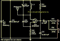
With this compact FM adapter circuit plugged into the audio out of your cassete player or i Pod out put,you can listen your favorite music on your car stereo.This circuit is very useful if your car stereo does not have an auxiliary in socket.The circuit is nothing buy an short range FM transmitter.The FM transmitter circuit is based on low power NPN transistor 2N2222.The tank circuit consisting of L1 & C1 produces the necessary oscillations at the collector of Q1.The capacitance C4 , resistance R3 & R4 performs the function of mixing the stereo out put from the audio player or i-Pod.The emitter resistance R2 provides sufficient stability to the circuit.It also limits the collector current to increase the battery life.
Notes.
* Use a 28SWG , 10 cm insulated copper wire as antenna.
* For L1.make 8 turns of 20 SWG insulated copper wire on a 5mm dia plastic former.
* Power the circuit from a 3V battery.
* Assemble the circuit on a good quality PCB or common board.
* C1 can be a 50pF trimmer.
|
Labels:
fm,
transmitter,
versatile
|
|
Here is the circuit diagram of a versatile FM transmitter that doesn’t have a coil. The circuit is simple and easy to assemble.
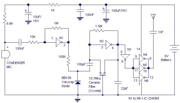
The gate N1 acts as a buffer for strengthening the signals from the condenser microphone. The inverter N2 with its associated components forms a radio frequency oscillator in the FM region.The varicap diode BB109 is used for frequency modulating the audio signal to the carrier wave generated by the oscillator.Inverters N4 t0 N6 are used to drive the antenna.As the N4,N5,N6 are connected in parallel their effective output impedance is very less and can easily drive the antenna.
Notes.
* All electrolytic capacitors must be rated 10V.
* Use any general purpose condenser microphone.You can easily get one from old telephone or tape recorder.
* Use a 10 cm long wire as antenna.
* Gates N1 to N6 belong to same IC CD4069.
* The battery can be a 9V transistor radio battery.Adapters are not recommended because they would induce noise in the circuit.
Continue reading...
|
Labels:
battery,
lamp,
night,
powered
|
|
This circuit is usable as a Night Lamp when a wall mains socket is not available to plug-in an ever running small neon lamp device. In order to ensure minimum battery consumption, one 1.5V cell is used and simple voltage doublers drives a pulsating ultra-bright LED: current drawing is less than 500µA. An optional Photo resistor will switch-off the circuit in daylight or when room lamps illuminate, allowing further current economy.
This device will run for about 3 months continuously on an ordinary AA sized cell or for around 6 months on an alkaline type cell but, adding the Photo resistor circuitry, running time will be doubled or, very likely, triplicates. IC1 generates a square wave at about 4 Hz frequencies. C2 & D2 form voltage doublers, necessary to raise the battery voltage to a peak value able to drive the LED.

|
Labels:
car,
diagrams,
wiring
|
|
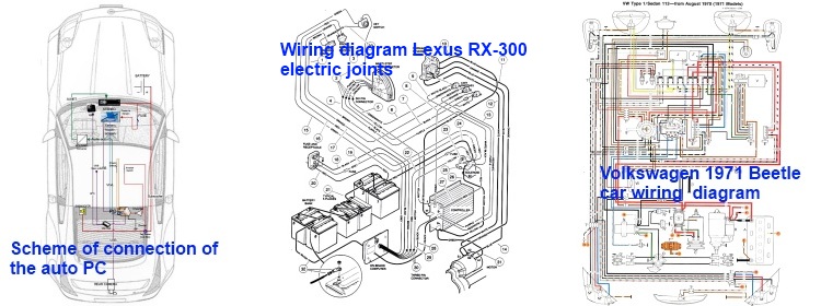
Acura wiring diagram, Audi wiring diagram, BMW wiring diagram, Chevrolet wiring diagram, Chrysler wiring diagram, Citroen wiring diagram, Daewoo wiring diagram, Dodge wiring diagram, Ford wiring diagram, Honda wiring diagram, Hyundai wiring diagram, Jaguar wiring diagram,
Jeep wiring diagram, Kia wiring diagram, Lexus wiring diagram, Lincoln wiring diagram, Mazda wiring diagram, Mercedes car wiring diagram, Mitsubishi car wiring diagram, Nissan car wiring diagram, Opel car wiring diagram, Peugeot wiring diagram, Pontiac wiring diagram, Renault wiring diagram, Rover wiring diagram, Saab wiring diagram, Seat wiring diagram, Skoda wiring diagram, Smart wiring diagram, Subaru wiring diagram, Toyota wiring diagram, Volkswagen wiring diagram, Volvo wiring diagram.


