Showing posts with label level. Show all posts

Subwoofer Speaker Level Input Output Connection

Tuesday, June 4, 2013 | Labels: , , , , , | 0 comments |
Subwoofer Wiring on How Do I Wire My Amp To A Sub    Faqs   Polk Audio
How Do I Wire My Amp To A Sub Faqs Polk Audio.


Subwoofer Wiring on Subwoofer Speaker Wiring Diagram   Subwoofer Review
Subwoofer Speaker Wiring Diagram Subwoofer Review.


Subwoofer Wiring on Click Here To Download The Swan Wiring Floor Plan Pdf
Click Here To Download The Swan Wiring Floor Plan Pdf.


Subwoofer Wiring on Subwoofer And Avr Speaker Level Input Output Connection
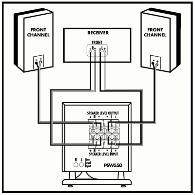
Subwoofer And Avr Speaker Level Input Output Connection.


Subwoofer Wiring on Breitbandtreiber Integrierter Subwoofer Downfired Woofer Bi Wiring
Breitbandtreiber Integrierter Subwoofer Downfired Woofer Bi Wiring.


Subwoofer Wiring on Sony Xs 4624 Coaxial 2 Way Speaker Subwoofer Wiring Diagram And Cable
Sony Xs 4624 Coaxial 2 Way Speaker Subwoofer Wiring Diagram And Cable.


Subwoofer Wiring on Subwoofer Wiring Diagram Made Simple
Subwoofer Wiring Diagram Made Simple.


Subwoofer Wiring on Amplifier Types  2 Channel 4 Channel Mono   Multi Channel Amps
Amplifier Types 2 Channel 4 Channel Mono Multi Channel Amps.


Subwoofer Wiring on Car Audio Capacitor Installation
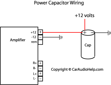
Car Audio Capacitor Installation.


Subwoofer Wiring on 2009 Sony Xplod Subwoofer And Amp For Sale   Octane Ie
2009 Sony Xplod Subwoofer And Amp For Sale Octane Ie.


Continue reading...

How to Make an Ideal Automatic Water Level Controller and Indicator Circuit

Monday, May 27, 2013 | Labels: , , , , , , , , , , , | 0 comments |
 This system monitors the water level of the tank and automatically switches ON the motor when ever tank is empty. The motor is switched OFF when the overhead tank or container is FULL. Here the water level of the tank is indicated on LCD (Liquid crystal Display). Using this system, we can avoid the overflow of the water. We have already seen How water level indicator circuit works using AVR Microcontroller in the earlier post. But, here we are designing the circuit which is used to detect and control the water level automatically in overhead tank using 8051 microcontroller.

In this system water sensing can be done by using a set of 4 wires which are placed at different levels in tank. DC supply probe is placed at the base of the tank.
Water Level Controller using 8051 Circuit Principle:

This system mainly works on a principle that “water conducts electricity”. The four wires which are dipped into the tank will indicate the different water levels. Based on the outputs of these wires, microcontroller displays water level on LCD as well as controls the motor.
Water Level Controller using 8051 Circuit Diagram: 


Circuit Components:

    At89c51 controller
    At89c51 programming board.
    16*2 LCD
    5V Relay
    Bc547 (NPN) transistors – 5
    Resistors (1K) – 4
    Resistor – 330 ohm
    AC Motor
    Pot – 10k
    Programming cable
    Connecting wires

Water Level Controller using 8051 Circuit Design:

The main heart of this project is AT89C51 microcontroller. The water level probes are connected to the P3.0, P3.1, P3.2, and P3.3 through the transistors. Port P2 connected to the data pins of LCD and control pins RS, RW and EN of LCD are connected to the P1.0, P1.1, and P1.2 respectively.

Initially when tank is empty, LCD will display the message EMPTY and motor runs automatically. When water level reaches to quarter level, now LCD displays QUARTER and still motor runs. For further levels, LCD displays the messages HALF and ¾ FULL.

When tank is full, LCD displays FULL and motor automatically stops. Again motor runs when tank is empty.

great idea from http://www.electronicshub.org/water-level-controller-using-8051-microcontroller/
Continue reading...

Remote Audio Level Indicator

Saturday, April 13, 2013 | Labels: , , , | 0 comments |
The standard degree-indicator circuits which can be available in the market require connections to be made to the output of the player, which may now not be simply accessible. The audio degree indicator circuit described right here take aways this limit as it can be placed on the topic of the participant’s audio system and yet the specified impact can be realised. 

Circuit diagram :

Remote Audio Level Indicator Circuit Diagram

As proven within the circuit, signals are picked up with the aid of the condenser microphone, which get further amplified through the noninverting amplifier built around one of the vital 4 op-amps of LM324. The remaining three, along with 4 op-amps of the 2nd LM324, are used as seven comparators to work as the degree detector, giving seven output degrees via seven colored LEDs. 

The sensitivity of the audio level indicator circuit is also superior by using various the 220k potentiometer. If a nice adjustment is desired, a four.7-kilohm potentiometer is also related in collection resistors with the 220k potentiometer.


Copyright : EFY
Continue reading...