Simple Bright Idea USB Lightbulb

Friday, September 26, 2014 | Labels: , , , , | 0 comments |
 Simple Bright Idea USB Lightbulb

Located right at the end of a sturdy and flexible arm, lies the Bright Idea USB Lightbulb which happens to be a fuss-free lamp, sans switches, where it will also not come with a lampshade nor any legs. No sir, it is up to that creative mind of yours to concentrate and deliberate over grand ideas.

 Simple Bright Idea USB Lightbulb

ou will find it emit a soft and soothing blue light as long as it remains plugged into any USB port, where it will shine some reassuring illumination whenever you need to work late into the night. Not only that, it will glow in the dark even when it is not plugged in, how about that for innovation
Continue reading...

Simple FM Transmitter Circuit Diagram

| Labels: , , , , | 0 comments |
This circuit is a simple two transistor (2N2222) FM transmitter. No license is required for this transmitter according to FCC regulations regarding wireless microphones. If powered by a 9 volt battery and used with an antenna no longer than 12 inches, the transmitter will be within the FCC limits.

The microphone is amplified by Q1. Q2, C5, and L1 form an oscillator that operates in the 80 to 130 MHz range. The oscillator is voltage controlled, so it is modulated by the audio signal that is applied to the base of Q2. R6 limits the input to the RF section, and its value can be adjusted as necessary to limit the volume of the input. L1 and C6 can be made with wire and a pencil. The inductor (L1) is made by winding two pieces of 24 gauge insulated wire, laid side by side, around a pencil six times. Remove the coil you have formed and unscrew the two coils apart from each other. 

  FM Transmitter Circuit Diagram

  FM Transmitter Circuit Diagram


One of these coils (the better looking of the two) will be used in the tank circuit, and the other can be used in the next one you build. The antenna (24 gauge wire) should be soldered to the coil you made, about 2 turns up from the bottom, on the transistor side, and should be 8-12 inches long. To make C6, take a 4 inch piece of 24 gauge insulated wire, bend it over double and, beginning 1/2" from the open end, twist the wire as if you were forming a rope. When you have about 1" of twisted wire, stop and cut the looped end off, leaving about 1/2" of twisted wire (this forms the capacitor) and 1/2" of untwisted wire for leads.
Continue reading...

Mini10 W Audio Amplifier

| Labels: , , , | 0 comments |
This design is based on the 18 Watt Audio Amplifier, and was developed mainly to satisfy the requests of correspondents unable to locate the TLE2141C chip. It uses the widespread NE5532 Dual IC but, obviously, its power output will be comprised in the 9.5 - 11.5W range, as the supply rails cannot exceed ±18V.

10 W Audio Amplifier Circuit Diagram

10 W Audio Amplifier Circuit Diagram


As amplifiers of this kind are frequently used to drive small loudspeaker cabinets, the bass frequency range is rather sacrificed. Therefore a bass-boost control was inserted in the feedback loop of the amplifier, in order to overcome this problem without quality losses. The bass lift curve can reach a maximum of +16.4dB @ 50Hz. In any case, even when the bass control is rotated fully counterclockwise, the amplifier frequency response shows a gentle raising curve: +0.8dB @ 400Hz, +4.7dB @ 100Hz and +6dB @ 50Hz (referred to 1KHz).

Notes:

  • Can be directly connected to CD players, tuners and tape recorders.
  • Schematic shows left channel only, but C3, C4, IC1 and the power supply are common to both channels.
  • Numbers in parentheses show IC1 right channel pin connections.
  • A log type for P2 will ensure a more linear regulation of bass-boost.
  • Do not exceed 18 + 18V supply.
  • Q3 and Q4 must be mounted on heatsink.
  • D1 must be in thermal contact with Q1.
  • Quiescent current (best measured with an Avo-meter in series with Q3 Emitter) is not critical.
  • Set the volume control to the minimum and R3 to its minimum resistance.
  • Power-on the circuit and adjust R3 to read a current drawing of about 20 to 25mA.
  • Wait about 15 minutes, watch if the current is varying and readjust if necessary.
  • A correct grounding is very important to eliminate hum and ground loops. Connect to the same point the ground sides of J1, P1, C2, C3 &C4. Connect C9 to the output ground.
  • Then connect separately the input and output grounds to the power supply ground.

Parts:

P1_________________22K   Log.Potentiometer (Dual-gang for stereo)
P2________________100K Log.Potentiometer (Dual-gang for stereo)
R1________________820R 1/4W Resistor
R2,R4,R8____________4K7 1/4W Resistors
R3________________500R 1/2W Trimmer Cermet
R5_________________82K 1/4W Resistor
R6,R7______________47K 1/4W Resistors
R9_________________10R 1/2W Resistor
R10__________________R22 4W Resistor (wirewound)

C1,C8_____________470nF 63V Polyester Capacitor
C2,C5_____________100µF 25V Electrolytic Capacitors
C3,C4_____________470µF 25V Electrolytic Capacitors
C6_________________47pF 63V Ceramic or Polystyrene Capacitor
C7_________________10nF 63V Polyester Capacitor
C9________________100nF 63V Polyester Capacitor

D1______________1N4148 75V 150mA Diode

IC1_____________NE5532 Low noise Dual Op-amp

Q1_______________BC547B 45V 100mA NPN Transistor
Q2_______________BC557B 45V 100mA PNP Transistor
Q3_______________TIP42A 60V 6A PNP Transistor
Q4_______________TIP41A 60V 6A NPN Transistor

J1__________________RCA audio input socket

Power supply parts:

R11_________________1K5  1/4W Resistor

C10,C11__________4700µF 25V Electrolytic Capacitors

D2________________100V 4A Diode bridge
D3________________5mm. Red LED

T1________________220V Primary, 12 + 12V Secondary 24-30VA Mains transformer

PL1_______________Male Mains plug

SW1_______________SPST Mains switch
 

Technical data:

Output power:
10 Watt RMS into 8 Ohm (1KHz sinewave)
Sensitivity:
115 to 180mV input for 10W output (depending on P2 control position)
Frequency response:
See Comments above
Total harmonic distortion @ 1KHz:
0.1W 0.009% 1W 0.004% 10W 0.005%
Total harmonic distortion @ 100Hz:
0.1W 0.009% 1W 0.007% 10W 0.012%
Total harmonic distortion @ 10KHz:
0.1W 0.056% 1W 0.01% 10W 0.018%
Total harmonic distortion @ 100Hz and full boost:
1W 0.015% 10W 0.03%
Max. bass-boost referred to 1KHz:
400Hz = +5dB; 200Hz = +7.3dB; 100Hz = +12dB; 50Hz = +16.4dB; 30Hz = +13.3dB
Unconditionally stable on capacitive loads
 
Continue reading...

Arduino Leonardo vs Uno

| Labels: , , , | 0 comments |
The Arduino team is now shipping their latest creation – the Leonardo. It is the first Arduino to use Atmelʼs ATmegaXU4 series chip with built-in USB. This change is big and it has big benefits. In addition to the built-in USB, it offers more digital and analog pins. This comprehensive guide gives you the details you need to know to start using it – pinout differences, hardware capabilities, new software libraries and more. [Link]
Arduino Leonardo vs Uno – What’s New
Continue reading...

Simple Remote control tester Circuit Diagram

| Labels: , , , , , | 0 comments |
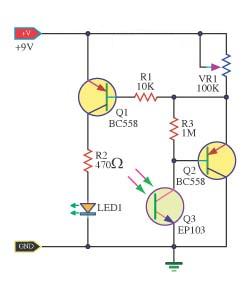
This is the simple Remote control tester circuit diagram. When the remote control is not working, first check the battery before, It may be loss.If it is good,so detect transmit infrared light device.However, because the human eye can not see infrared light,so can not know how good or bad.But the photo transistor can use to detect infrared light. 

This circuit so use this photo transistor is the light receiver from the remote control.If it is nice to have the bias current of the transistor BC558.It runs a current flows through the LED,so the LED bright.The remote control that works correctly. The variable resistor VR1 is used to adjust the sensitivity of the circuit.

 Remote control tester circuit diagram
 
 Remote control tester circuit diagram
Continue reading...

Scalable 12V Solar Power System and Battery Charge Controller

| Labels: , , , , , , , , | 0 comments |
An unconventional, scalable high efficiency 12V solar power system and battery charge controller with low voltage cutout to protect the battery. (ideal for systems of 50W or less). The most common solar charger consists of a Schottky diode to prevent the battery from draining into the PV panel and a shunt regulator that effectively short circuits the panel once the battery is fully charged.

Scalable 12V Solar Power System and Battery Charge Controller

One problem with this approach is diode losses and the resulting heat. If a 50W 12V panel supplies 4A to the battery, the Schottky diode will drop about 0,4V across it dissipating about 1,6W of heat. This requires a heat sink and loses power to heat. The problem is that there is no way of reducing the volt drop, paralleling diodes may share current, but the 0,4V will still be there. The circuit uses a MOSFET in stead of the usual diode and the primary power loss is resistive. [Link]
Continue reading...

A Li Ion Battery Charger with Load Sharing MCP73837

| Labels: , , , , , , , , | 0 comments |
Batteries often serve as the main energy source for portable electronic devices. Although they depend on batteries, portable consumer electronic products, such as GPS devices and multi-media players, often consume energy directly from an ac-dc wall adapter or accessory power adapter (or “Auto Adapter”) when the battery is low or the device is in a stationary mode. Due to their cost effectiveness over their useful life, rechargeable batteries are often used for the power source of the portable electronic device.


Designing A Li-Ion Battery Charger with Load Sharing - MCP73837

 
Attributes such as “relatively high energy density” and “maintenance free” make Lithium-Ion (Li-Ion) batteries popular in the portable consumer electronic products. Refer to the application note, AN1088, “Selecting the Right Battery System For cost Sensitive Portable Applications While maintaining Excellent Quality” (DS01088) for characteristics of Li-Ion batteries. Some examples of how to properly design with Li-Ion batteries will be discussed in this application note. [Link]
Continue reading...