Showing posts with label audio. Show all posts

Expensive DVD Player by Meridian Audio

Friday, September 26, 2014 | Labels: , , , , , | 0 comments |
Who doesnt have a DVD player today! I know, everybody has one, but I wonder who will have a DVD Player for $20,000! Yes, you read it right. Meridian Audio Ltd presents to you their exclusive range of DVD Players. The company manufactures the worlds most expensive DVD playback machine with prices starting at $19,950.

Worlds Most Expensive DVD Player by Meridian Audio for $20,000!

I am sure you must be thinking of what will you get in return for $20,000! Robert Stuart, the co-founder of Meridian rephrased the question to What do you get for so little? The Model 800 DVD Player is believed to be the pinnacle in audio and video processing technologies. The player plays video recorded in the American NTSC and European PAL systems and uses proprietary software to decode the audio, complex processing to increase picture resolution and extra buffer memory.

So, if you are the one who have a passion for all the most expensive stuff then this superb high definition DVD Player is just for your HDTV!!!![via]
Continue reading...

Mini10 W Audio Amplifier

| Labels: , , , | 0 comments |
This design is based on the 18 Watt Audio Amplifier, and was developed mainly to satisfy the requests of correspondents unable to locate the TLE2141C chip. It uses the widespread NE5532 Dual IC but, obviously, its power output will be comprised in the 9.5 - 11.5W range, as the supply rails cannot exceed ±18V.

10 W Audio Amplifier Circuit Diagram

10 W Audio Amplifier Circuit Diagram


As amplifiers of this kind are frequently used to drive small loudspeaker cabinets, the bass frequency range is rather sacrificed. Therefore a bass-boost control was inserted in the feedback loop of the amplifier, in order to overcome this problem without quality losses. The bass lift curve can reach a maximum of +16.4dB @ 50Hz. In any case, even when the bass control is rotated fully counterclockwise, the amplifier frequency response shows a gentle raising curve: +0.8dB @ 400Hz, +4.7dB @ 100Hz and +6dB @ 50Hz (referred to 1KHz).

Notes:

  • Can be directly connected to CD players, tuners and tape recorders.
  • Schematic shows left channel only, but C3, C4, IC1 and the power supply are common to both channels.
  • Numbers in parentheses show IC1 right channel pin connections.
  • A log type for P2 will ensure a more linear regulation of bass-boost.
  • Do not exceed 18 + 18V supply.
  • Q3 and Q4 must be mounted on heatsink.
  • D1 must be in thermal contact with Q1.
  • Quiescent current (best measured with an Avo-meter in series with Q3 Emitter) is not critical.
  • Set the volume control to the minimum and R3 to its minimum resistance.
  • Power-on the circuit and adjust R3 to read a current drawing of about 20 to 25mA.
  • Wait about 15 minutes, watch if the current is varying and readjust if necessary.
  • A correct grounding is very important to eliminate hum and ground loops. Connect to the same point the ground sides of J1, P1, C2, C3 &C4. Connect C9 to the output ground.
  • Then connect separately the input and output grounds to the power supply ground.

Parts:

P1_________________22K   Log.Potentiometer (Dual-gang for stereo)
P2________________100K Log.Potentiometer (Dual-gang for stereo)
R1________________820R 1/4W Resistor
R2,R4,R8____________4K7 1/4W Resistors
R3________________500R 1/2W Trimmer Cermet
R5_________________82K 1/4W Resistor
R6,R7______________47K 1/4W Resistors
R9_________________10R 1/2W Resistor
R10__________________R22 4W Resistor (wirewound)

C1,C8_____________470nF 63V Polyester Capacitor
C2,C5_____________100µF 25V Electrolytic Capacitors
C3,C4_____________470µF 25V Electrolytic Capacitors
C6_________________47pF 63V Ceramic or Polystyrene Capacitor
C7_________________10nF 63V Polyester Capacitor
C9________________100nF 63V Polyester Capacitor

D1______________1N4148 75V 150mA Diode

IC1_____________NE5532 Low noise Dual Op-amp

Q1_______________BC547B 45V 100mA NPN Transistor
Q2_______________BC557B 45V 100mA PNP Transistor
Q3_______________TIP42A 60V 6A PNP Transistor
Q4_______________TIP41A 60V 6A NPN Transistor

J1__________________RCA audio input socket

Power supply parts:

R11_________________1K5  1/4W Resistor

C10,C11__________4700µF 25V Electrolytic Capacitors

D2________________100V 4A Diode bridge
D3________________5mm. Red LED

T1________________220V Primary, 12 + 12V Secondary 24-30VA Mains transformer

PL1_______________Male Mains plug

SW1_______________SPST Mains switch
 

Technical data:

Output power:
10 Watt RMS into 8 Ohm (1KHz sinewave)
Sensitivity:
115 to 180mV input for 10W output (depending on P2 control position)
Frequency response:
See Comments above
Total harmonic distortion @ 1KHz:
0.1W 0.009% 1W 0.004% 10W 0.005%
Total harmonic distortion @ 100Hz:
0.1W 0.009% 1W 0.007% 10W 0.012%
Total harmonic distortion @ 10KHz:
0.1W 0.056% 1W 0.01% 10W 0.018%
Total harmonic distortion @ 100Hz and full boost:
1W 0.015% 10W 0.03%
Max. bass-boost referred to 1KHz:
400Hz = +5dB; 200Hz = +7.3dB; 100Hz = +12dB; 50Hz = +16.4dB; 30Hz = +13.3dB
Unconditionally stable on capacitive loads
 
Continue reading...

Simple 25W Audio Power Amplifier Circuit

Friday, September 19, 2014 | Labels: , , , , , | 0 comments |
This audio power amplifier project is based on LM1875 amplifier module from National Semiconductor. It can deliver up to 30W of power using an 8 ohm load & dual 30V DC power supplies. It is designed to operate with maximum outside parts with current limit & thermal shutdown protection features . Other features include high gain, quick slew rate, wide power supply range, giant output voltage swing & high current capability.

Summary of the audio amply-fire features:

  • Low distortion: 0.015%, 1 kHz, 20 W
  • Wide power bandwidth: 70 kHz
  • Wide supply range 16V-60V
  • Up to 30 watts output power
  • Internal output protection diodes
  • Protection for AC & DC short circuits to ground
  • 94 dB ripple rejection
  • Plastic power package TO-220
25V Power Supply

The schematic below shows how the +25V DC & -25V DC are obtained. In order to provide power supply for two stereo amplifiers, a power transformer rating of 80VA with 240V/36V middle tapped secondary winding is used. The secondary output of the transformer is rectified by using 1N5401 diodes together with four electrolytic capacitors to smoother the ripple voltage. A fuse & a varistor are connected at the primary input to protect the circuit against power surge.


Audio Amplifier Module

The +25V & -25V DC power supply are connected to the audio amplifier module through a 2A fuse with the peripheral devices shown in the schematic below. The audio input signal to be amplified is coupled to pin one of LM1875 through the resistor R1 and electrolytic capacitor E5.

The output signal at pin four of LM1875 can be used to directly drive a 8 ohm loudspeaker. Resistor R6 and capacitor C5 prevent-the capacitance developed at the long speaker leads from driving the amplifier in to High Frequency Oscillation.

A heat-sink with a thermal resistance rating of one.4 Cecilius/Watt or better must be used or else the amplifier module will-be cut-off from operation due to the heat that will build up in the coursework of the operation of the amplifier. Take note that the heat sink tab on the IC module is internally connected to the -25V power supply hence it must be isolated from the heat sink by the use of an insulating washer. If this is not done, the negative rail will be shorted to ground.


Sourced By: Streampowers.blogspot.com
Continue reading...

Audio Parallel Speaker Wiring Diagram

Friday, May 31, 2013 | Labels: , , , , | 0 comments |
Telephone Wiring on Car Audio Parallel Speaker Wiring Diagram
Car Audio Parallel Speaker Wiring Diagram.


Telephone Wiring on Rj 11 4 Pair Phone Wiring Color Codes And Diagram   Circuit Schematic
Rj 11 4 Pair Phone Wiring Color Codes And Diagram Circuit Schematic.


Telephone Wiring on Telephone Wiring And One Jack Not Working   Ask Me Help Desk
Telephone Wiring And One Jack Not Working Ask Me Help Desk.


Telephone Wiring on Uk Telephone Wiring
Uk Telephone Wiring.


Telephone Wiring on Get More Information Regarding The Home Phone Wiring Diagram Using
Get More Information Regarding The Home Phone Wiring Diagram Using.


Telephone Wiring on Data   Telephone Wiring Standards
Data Telephone Wiring Standards.


Telephone Wiring on Lju 2 3a Telephone Extension Socket Telephone Wiring
Lju 2 3a Telephone Extension Socket Telephone Wiring.


Telephone Wiring on Telephone Socket Wiring Diagram
Telephone Socket Wiring Diagram.


Telephone Wiring on Doing Your Own Telephone Wiring
Doing Your Own Telephone Wiring.


Telephone Wiring on Mode 3 Telephone Connector   C Bus Forums
Mode 3 Telephone Connector C Bus Forums.


Continue reading...

Dual Polarity Unregulated PSU For High End Audio Amps

Wednesday, May 29, 2013 | Labels: , , , , , , , , | 0 comments |
A power supply suitable for use with the hi-fi amplifiers presented in the predeeding project is perfectly simple, and no great skill is required to build (or design) one. There are a few things one should be careful with, such as the routing of high current leads, but these are easily accomplished. Design of this power supply is very simple. A 4 ampere fuse is used to protect the transformer and two LEDs at the end of this circuit are used to indicate power state On and Off. At the ouptut there are 6 capacitors used you can reduce the quantity of these filter capacitors to 2 or according to your own choice.

click on the images to enlarge
Continue reading...

LM3875 High Audio Amplifier 56W

Friday, May 17, 2013 | Labels: , , , , | 0 comments |
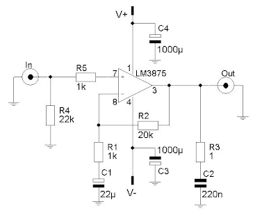
LM3875-High Audio Amplifier 56W
The LM3875 is an audio amplifier for high power output capable of delivering 56W of continuous average power to a load 8. The performance of the LM3875, utilizing its maximum instantaneous auto temperature (° Ke) (Spike ™) protection circuitry, places it in a class above discrete and hybrid amplifiers by providing a yes, dynamically protected area of safe operation (SOA). SPIKE protection means that these parts are fully protected against output overvoltage, voltage surges caused by shorts to the supplies, the peak temperature thermal runaway, and instantaneous.

This amplifier circuit is based on the non-inverted GainClone standard configuration. I did some calucaltions the feedback resistor and other components in order to check the gain, etc. For more background on the calculations relevant to GainClones in the background section.

LM3875-High Audio Amplifier 56WParameters IC LM3875

Output Current 6000 mA.
Offset Voltage max, 25C 10 mV.
Gain Bandwidth 8 MHz.
Supply Min 20 Volt.
Supply Max 84 Volt.
Supply Current Per Channel 30 mA.
PowerWise Rating 2 3750 uA/MHz.
Slew Rate 11 Volts/usec.
Input OutputType Not Rail to Rail.
Max Input Bias Current 1000 nA.
Special Features AvCl>10.
Function Op Amp.
Channels 1 Channels.
Temperature Min 0 deg C.
Temperature Max 70 deg C.
Continue reading...

Small Audio Amplifiers Using LM386 and NE5534

Tuesday, April 30, 2013 | Labels: , , , , , , | 0 comments |
Many electronic projects require the use of a small audio amplifier. Be it a radio transceiver, a digital voice recorder, or an intercom, they all call for an audio amp that is small, cheap, and has enough power to provide adequate loudness to fill a room, without pretending to serve a disco! About one Watt RMS seems to be a convenient size, and this is also about the highest power that a simple amplifier fed from 12V can put into an 8 Ohm speaker. A very low saturation amplifier may go as high up as 2 Watt, but any higher power requires the use of a higher voltage power supply, lower speaker impedance, a bridge circuit, or a combination of those.

During my many years building electronic things I have needed small audio amps many times, and have pretty much standardized on a few IC solutions, first and and foremost the LM386, which is small, cheap, and very easy to use. But it does not produce high quality audio... For many applications, the advantages weigh more than the distortion and noise of this chip, so that I used it anyway. In other cases I used different chips, which perform better but need more complex circuits. Often these chips were no longer available the next time I needed a small amplifier.

When I last upgraded my computer, I replaced the old and trusty Soundblaster AWE 32 by a Soundblaster Audigy. The new card is better in many regards, but while the old one had an internal audio power amplifier, the new one doesnt! Thats bad news, because I have some pretty decent speakers for the PC, which are fully passive. So, I built a little stereo amp using two LM386 chips and installed it inside the computer, fed by the 12V available internally.

But then I wasnt satisfied. The LM386 might be suitable for "communication quality" audio, which is roughly the fidelity you get over a telephone, but for music its pretty poor! The distortion was awful. So, the day came when I decided to play a little more scientifically with small audio amps, looking for a way to get good performance with simple and inexpensive means.

I set up a test bench with a sine wave oscillator running at 1 kHz, an 8 Ohm speaker, 12V power supply, and the computer with the soundcard and Fast Fourier Transform software. One channel was connected to the oscillator together with the amplifier input, the other channel to the output and speaker. With this setup I measured the harmonic content of the audio signals. I did the tests at an output level of 0.1W, which is typical for moderately loud sound from a reasonably efficient speaker. Also, I used a music signal from a CD player to test the actual sound of each amplifier.

Circuit Project: Small Audio Amplifiers Using LM386 and NE5534

As already said above, the main attraction of the LM386 is the extreme simplicity of its application circuit. You can even eliminate R1 if the signal source is DC-grounded. If the speaker leads are long, you should add an RC snubber across the output to aid stability. Additionally, if you need higher gain (not necessary if the input is at line level), you can connect a 10uF capacitor between pins 1 and 8. Thats about all there is to it.

Now the bad news: This circuit produced a very high level of distortion! The second harmonic measured just -28dB from the main output. The third harmonic was at -35dB, while the noise level was at -82dB. There were assorted high harmonics at roughly -45dB. With music, the distortion was really disturbing, and also the noise level was uncomfortably high. The power supply rejection is poor, so that some hum and other supply noise gets through. In short, this was a lousy performance!

Since I had used so many LM386s in my projects, I had several different variations. In my material box I found a slightly newer LM386N-1. So I plugged it into my test amplifier. It was even worse! The second harmonic was at -24dB, the third harmonic at -31dB, while the noise was a tad better at -84dB. Folks, thats a total harmonic distortion of almost 7%! And the 0.1W output level at which this was measured is where such a circuit is about at its best...  The distortion can be plainly seen on the oscilloscope, and a visibly distorted waveform is about the most offending thing an audio designer can ever see!

Looking through my projects, I found one where I had used a GL386 chip. This is just a 386 made by another company. I unsoldered it and put it in my test amplifier. Surprise! It was dramatically better, with the second harmonic at -45dB, and the third at -57dB! The noise floor was -84dB, just like the LM386N-1. But even this level of distortion was plainly audible when listening to music. Thats roughly 0.6% THD. Some folks may consider it acceptable for music. I dont, but for communication equipment its fine. At this point, I decided to see if I could build a better amplifier, that doesnt become too complex nor expensive.

Circuit Project: Small Audio Amplifiers Using LM386 and NE5534

This was the first attempt. A low distortion, fast slew rate, but easy to find and rather inexpensive operational amplifier, driving a simple source follower made of two small transistors. These transistors are not biased, so they work at zero quiescent current, in full class B. The only mechanism that works against crossover distortion here is the high slew rate of the OpAmp, which is able to make the distortion bursts during crossover very short. To say the truth, I didnt expect to get usable performance from this circuit, and was really surprised when it worked much better than the 386! The second harmonic was at -77dB, the third at -79dB!

Also there were many high harmonics at roughly -84dB. That means a THD of about 0.015%.  The noise floor was down at the -120dB level! The power supply rejection was excellent, with no detectable feedtrough. Playing music, this amplifier sounded really good: No audible noise, and the distortion could be heard when paying attention to it, but I doubt that the average person would detect it! Not bad, for a bias-less design!

Just to see how important the slew rate of the OpAmp is, I pulled out the NE5534 and replaced it by a humble 741, which is many times slower. The result was dramatic: The second harmonic still good at -70dB, but the third harmonic was much worse, at -48dB. Also there were many high harmonics at the same -48dB level. Given that second harmonic distortion doesnt sound bad to most people, but third harmonic does, and high harmonics are even worse, it came as no surprise that the amplifier with the 741 sounded bad.

At low volume it sounded particularly bad! So I returned to the oscillator and measurement setup, testing at lower output power, and found that while the second and third harmonics followed the output, the high harmonics stayed mostly constant! So, at very low output, the high harmonics became very strong relative to the output. All this is the effect of the slower slew rate of the 741, which makes it less effective correcting the crossover distortion of the unbiased transistors. Interestingly, the noise floor of the 741 circuit wasnt bad: -118dB.

Just for fun, I tried this circuit with a third OpAmp: The TL071, which is good, but not as good as the 5534. The results: Second harmonic at -72dB, third and the high ones at -60dB, and the noise at -120dB. Its interesting that the second harmonic is much more suppressed than the third one. That must be a balancing effect of the symmetric output stage, and the better symmetry in the TL071 compared to other OpAmps.

Its worthwhile to note that this amplifier can be simplified a lot by using a split power supply. R1, R2, C1, C2 and C4 would be eliminated! But then you need the capacitor removed from C4 to bypass the negative supply line. The positive input of the chip goes to ground, while pin 4 and the collector of Q2 go to the negative supply. The rest stays the same. If you use a +-15V supply, the available RMS output power grows to over 10 Watt! Of course, you then need larger transistors. And since larger transistors are slower, the distortion will rise somewhat. An added benefit of a split supply is that the popping noise when switching on and off is eliminated.

Circuit Project: Small Audio Amplifiers Using LM386 and NE5534

As the next experiment, I decided to get rid of the crossover distortion. For this purpose, I added a traditional adjustable bias circuit with a transistor and a trimpot. Now I also had to add a current source, because with the bias circuit there is no single point into which the OpAmp could put its drive current into both bases! I adjusted the bias for the best distortion, and this was really  a good one! The second harmonic was down right where the test oscillator delivered it, about -80dB, so I couldnt really measure it!

The third harmonic was at -84dB, and the best improvement was that the higher harmonics had simply disappeared! They were all below the noise floor, which stayed at -120dB. Actually, this noise floor seems to come from the soundcard A/D converter, so that the actual noise of this and the above amplifier may even be better! With music, this amplifier sounded perfect - clean and smooth. And Im pretty confident that the THD is well below the limits of my measurement setup, which is 0.01%.

The quiescent current was around 10mA. When lowering it to about 3mA, the high harmonics started to rise out of the noise floor. If you want to adjust the bias for the exact best quiescent current, there is a simple trick: Lift R4 from the output, and connect it to pin 6. Now the output stage has been left outside the feedback loop, and all its distortion will show up at the output. Watching the signal on an oscilloscope, or even better on a real time spectrum analyzer (soundcard and software), adjust the trimpot to the lowest distortion level.

Have a current meter in the supply line and make sure that you dont exceed 30mA or so of quiescent current, in order to keep the small transistors cool. But most likely the best distortion will be at a current lower than that. Once the adjustment is complete, return R4 to its normal position. Now the full gain and slew rate of the operational amplifier is used to correct the small remaining cross-over distortion of the output stage, and the distortion will certainly disappear from the scope screen, from your ears, and possibly fall below the detection level of the spectrum analyzer!

This circuit can also be run from a split power supply, by exactly the same mods as for the previous circuit. And since the transistors are properly biased, there isnt any significant distortion increase when using larger transistors. Be sure to use some that have enough gain - you have only a few mA of driving available, and with a +-15V power supply and an 8 Ohm speaker, there can be almost 2A of output current! So, you need a gain of 300 at least. There are power transistors in the 4A class that provide such gain, and these are good candidates. The other option is using Darlington transistors, which far exceed the gain needed here. But they will again increase the distortion, not very much, but perhaps enough to make it audible again.
 
 
Source: Humo Luden
Continue reading...

Remote Audio Level Indicator

Saturday, April 13, 2013 | Labels: , , , | 0 comments |
The standard degree-indicator circuits which can be available in the market require connections to be made to the output of the player, which may now not be simply accessible. The audio degree indicator circuit described right here take aways this limit as it can be placed on the topic of the participant’s audio system and yet the specified impact can be realised. 

Circuit diagram :

Remote Audio Level Indicator Circuit Diagram

As proven within the circuit, signals are picked up with the aid of the condenser microphone, which get further amplified through the noninverting amplifier built around one of the vital 4 op-amps of LM324. The remaining three, along with 4 op-amps of the 2nd LM324, are used as seven comparators to work as the degree detector, giving seven output degrees via seven colored LEDs. 

The sensitivity of the audio level indicator circuit is also superior by using various the 220k potentiometer. If a nice adjustment is desired, a four.7-kilohm potentiometer is also related in collection resistors with the 220k potentiometer.


Copyright : EFY
Continue reading...

25W Audio Power Amplifier Rise

Friday, April 12, 2013 | Labels: , , , , | 0 comments |
This audio energy amplifier undertaking is based on LM1875 amplifier module from National Semiconductor. It can deliver as so much as 30W of energy the utilization of an 8 ohm load & twin 30V DC power provides. It is designed to operate with most outdoor parts with current limit & thermal shutdown protection features . Other features include high achieve, fast slew charge, huge energy provide vary, giant output voltage swing & high present functionality.

Summary of the audio amply-fire options:

  • Low distortion: 0.015%, 1 kHz, 20 W
  • Wide power bandwidth: 70 kHz
  • Wide supply range 16V-60V
  • Up to 30 watts output energy
  • Internal output safety diodes
  • Protection for AC & DC brief circuits to floor
  • 94 dB ripple rejection
  • Plastic energy bundle TO-220
25V Power Supply

The schematic beneath shows how the +25V DC & -25V DC are acquired. In order to provide power provide for two stereo amplifiers, a power transformer score of 80VA with 240V/36V middle tapped secondary winding is used. The secondary output of the transformer is rectified by using 1N5401 diodes along side four electrolytic capacitors to smoother the ripple voltage. A fuse & a varistor are related at the major enter to give protection to the circuit once morest energy surge.


Audio Amplifier Module

The +25V & -25V DC power provide are related to the audio amplifier module thru a 2A fuse with the peripheral tools shown in the schematic under. The audio enter signal to be amplified is coupled to pin one among LM1875 throughout the resistor R1 and electrolytic capacitor E5.

The output sign at pin four of LM1875 can be utilized to immediately drive a eight ohm loudspeaker. Resistor R6 and capacitor C5 prevent-the capacitance developed on the lengthy speaker leads from riding the amplifier in to High Frequency Oscillation.

A heat-sink with a thermal resistance ranking of one.4 Cecilius/Watt or better should be used or else the amplifier module will-be cut-off from operation because of the heat in an effort to build up in the directionwork of the operation of the amplifier. Take note that the warmth sink tab on the IC module is internally related to the -25V power supply hence it must be remoted from the warmth sink by the use of an insulating washer. If this isn't finished, the negative rail shall be briefed to ground.


Continue reading...